
How to Use TFT SPI 1.8: Examples, Pinouts, and Specs
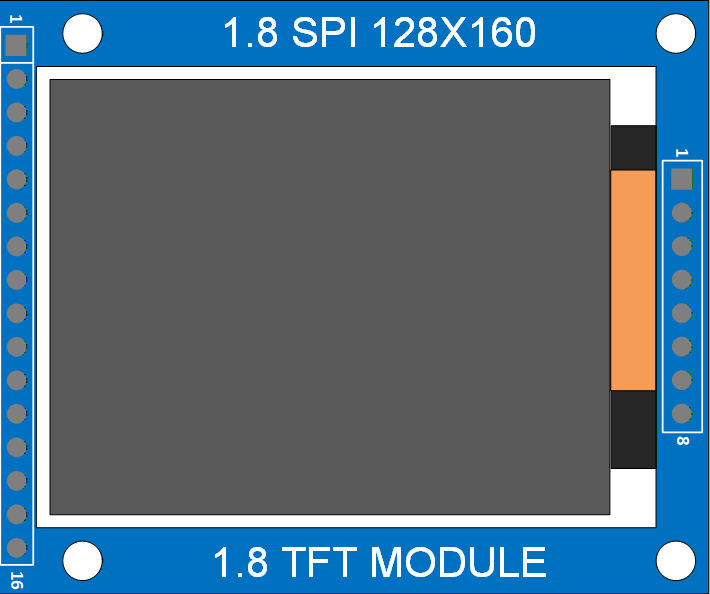
 Design with TFT SPI 1.8 in Cirkit Designer
Introduction
The TFT SPI 1.8 is a compact 1.8-inch thin-film transistor (TFT) display module that utilizes the Serial Peripheral Interface (SPI) for communication. This display is widely used in embedded systems and microcontroller projects due to its efficient data transfer capabilities and vibrant color rendering. It is ideal for applications requiring graphical interfaces, such as IoT devices, handheld gadgets, and DIY electronics projects.
Explore Projects Built with TFT SPI 1.8
 Open Project in Cirkit Designer
 Open Project in Cirkit Designer
 Open Project in Cirkit Designer
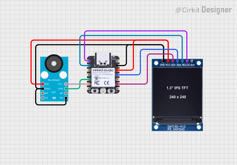 Open Project in Cirkit Designer
Explore Projects Built with TFT SPI 1.8
Open Project in Cirkit DesignerOpen Project in Cirkit DesignerOpen Project in Cirkit DesignerOpen Project in Cirkit DesignerCommon Applications
- Graphical user interfaces for embedded systems
- Display modules for IoT devices
- Portable electronics and handheld devices
- Educational and DIY electronics projects
- Real-time data visualization
Technical Specifications
Below are the key technical details and pin configuration for the TFT SPI 1.8 display module:
Key Technical Details
| Parameter | Specification |
|---|---|
| Display Type | TFT LCD |
| Screen Size | 1.8 inches |
| Resolution | 128 x 160 pixels |
| Communication Protocol | SPI |
| Operating Voltage | 3.3V (logic) |
| Backlight Voltage | 3.3V to 5V |
| Current Consumption | ~50mA (typical) |
| Color Depth | 18-bit (262,144 colors) |
| Controller IC | ST7735 |
| Operating Temperature | -20°C to 70°C |
Pin Configuration
| Pin Name | Pin Number | Description |
|---|---|---|
| GND | 1 | Ground connection |
| VCC | 2 | Power supply (3.3V or 5V for backlight) |
| SCL | 3 | Serial Clock (SPI clock input) |
| SDA | 4 | Serial Data (SPI data input) |
| RES | 5 | Reset pin (active low) |
| DC | 6 | Data/Command control pin |
| CS | 7 | Chip Select (active low) |
| LED | 8 | Backlight control (connect to VCC for always on) |
Usage Instructions
How to Use the TFT SPI 1.8 in a Circuit
- Power Supply: Connect the
VCCpin to a 3.3V or 5V power source and theGNDpin to ground. - SPI Connections:
- Connect the
SCLpin to the SPI clock pin of your microcontroller. - Connect the
SDApin to the SPI MOSI (Master Out Slave In) pin.
- Connect the
- Control Pins:
- Connect the
RESpin to a GPIO pin for resetting the display. - Connect the
DCpin to a GPIO pin to toggle between data and command modes. - Connect the
CSpin to a GPIO pin to enable or disable the display.
- Connect the
- Backlight: Connect the
LEDpin to VCC for constant backlight or to a PWM pin for brightness control.
Important Considerations
- Ensure the logic level of your microcontroller matches the display's operating voltage (3.3V). Use a level shifter if necessary.
- Use decoupling capacitors near the power pins to reduce noise.
- Avoid prolonged exposure to high temperatures to prevent damage to the display.
Example Code for Arduino UNO
Below is an example of how to interface the TFT SPI 1.8 with an Arduino UNO using the Adafruit ST7735 library:
#include <Adafruit_GFX.h>    // Core graphics library
#include <Adafruit_ST7735.h> // Hardware-specific library for ST7735

// Define TFT pins
#define TFT_CS     10  // Chip Select pin
#define TFT_RST    9   // Reset pin
#define TFT_DC     8   // Data/Command pin

// Initialize the display
Adafruit_ST7735 tft = Adafruit_ST7735(TFT_CS, TFT_DC, TFT_RST);

void setup() {
  // Initialize serial communication for debugging
  Serial.begin(9600);
  Serial.println("TFT SPI 1.8 Test");

  // Initialize the display
  tft.initR(INITR_BLACKTAB); // Initialize with ST7735 settings
  tft.fillScreen(ST7735_BLACK); // Clear the screen with black color

  // Display a message
  tft.setTextColor(ST7735_WHITE); // Set text color to white
  tft.setTextSize(1);             // Set text size
  tft.setCursor(0, 0);            // Set cursor position
  tft.println("Hello, TFT!");     // Print text to the display
}

void loop() {
  // Add your code here for dynamic updates
}
Best Practices
- Use a stable power supply to avoid flickering or instability.
- Keep SPI wires as short as possible to reduce noise and signal degradation.
- Use proper pull-up or pull-down resistors if required by your circuit design.
Troubleshooting and FAQs
Common Issues and Solutions
Display Not Turning On:
- Verify the power connections (
VCCandGND). - Ensure the
CSpin is properly configured and set low to enable the display.
- Verify the power connections (
Flickering or Unstable Display:
- Check for loose connections or poor solder joints.
- Use decoupling capacitors near the power pins to stabilize the voltage.
No Output or Incorrect Colors:
- Ensure the SPI connections (
SCLandSDA) are correctly wired. - Verify that the correct initialization settings are used in the code.
- Ensure the SPI connections (
Backlight Not Working:
- Confirm the
LEDpin is connected toVCCor a PWM pin. - Check the backlight voltage (3.3V to 5V).
- Confirm the
FAQs
Q: Can I use the TFT SPI 1.8 with a 5V microcontroller?
A: Yes, but you must use level shifters for the SPI and control pins to avoid damaging the display.
Q: What is the maximum SPI clock speed supported?
A: The display typically supports SPI clock speeds up to 15 MHz, but check the datasheet for your specific module.
Q: Can I control the backlight brightness?
A: Yes, connect the LED pin to a PWM-capable pin on your microcontroller to adjust brightness.
Q: Is the TFT SPI 1.8 compatible with Raspberry Pi?
A: Yes, it can be used with Raspberry Pi, but you may need to configure the SPI interface and use appropriate libraries.
This concludes the documentation for the TFT SPI 1.8 display module.