How to Use Splicing connector WAGO 221: Examples, Pinouts, and Specs
Introduction
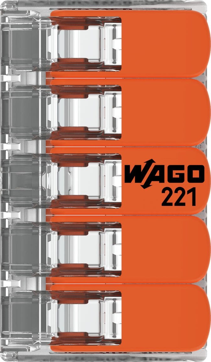
The WAGO 221-415 splicing connector is a compact, innovative, and reliable solution for connecting electrical wires. This connector is designed for ease of use, providing a secure connection without the need for stripping wire insulation. It is widely used in various applications, including residential, commercial, and industrial electrical installations, as well as in DIY projects and with hobbyist platforms like Arduino.
Explore Projects Built with Splicing connector WAGO 221
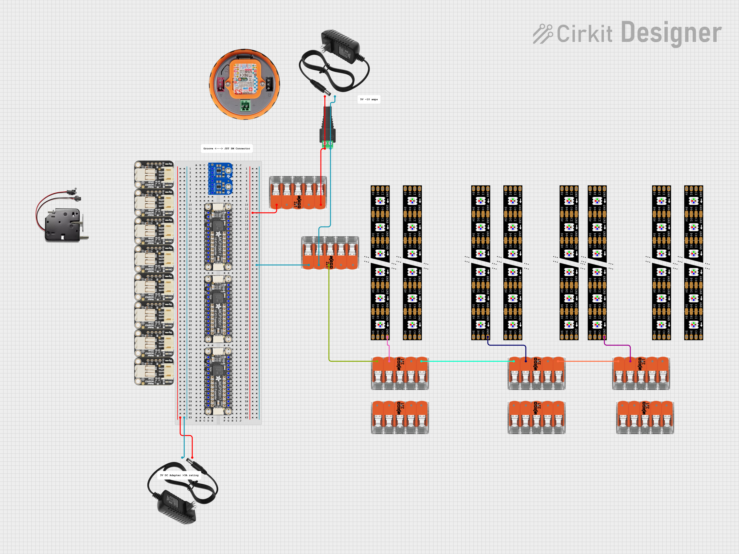
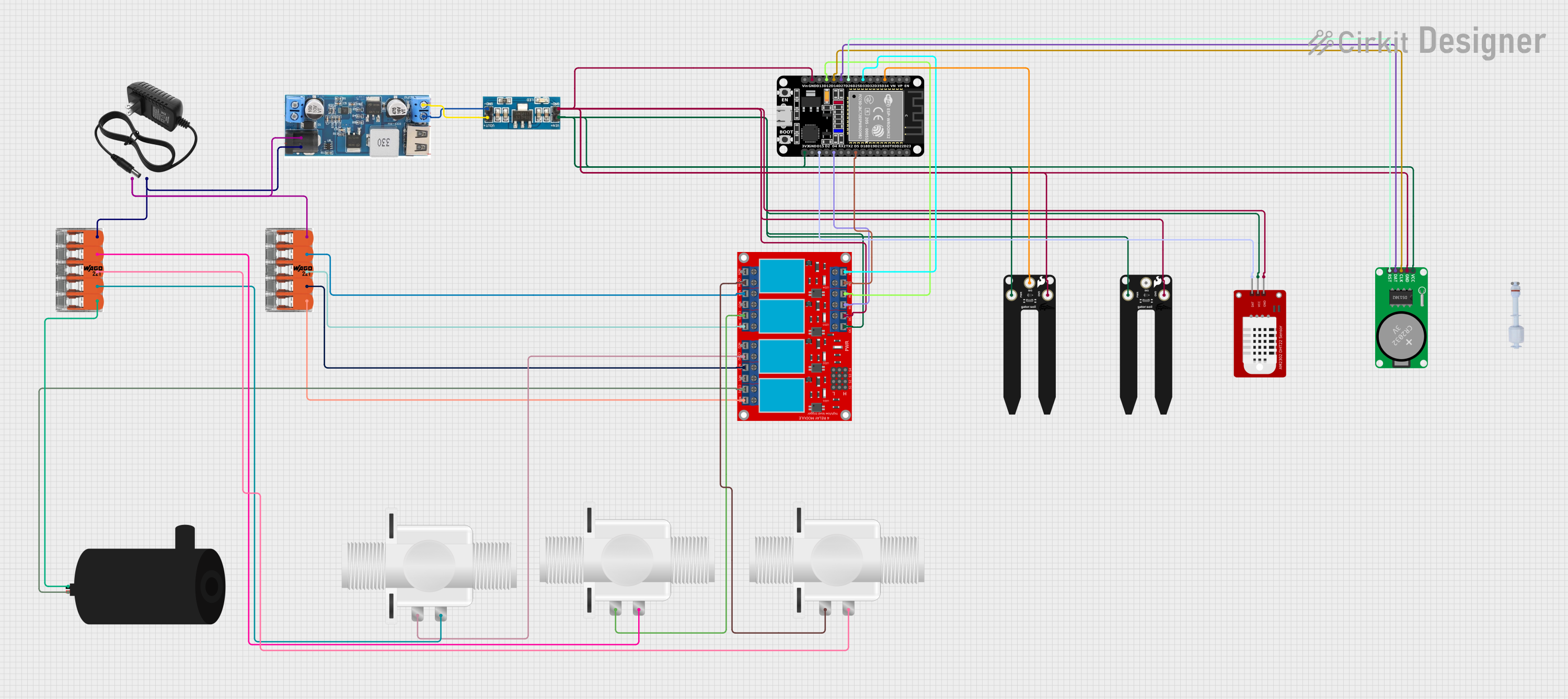
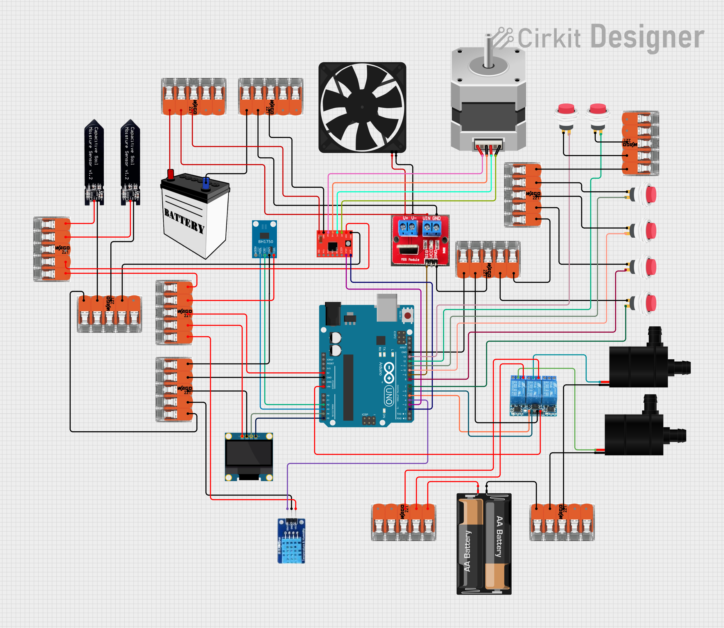
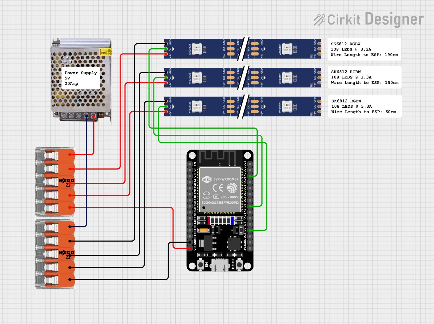
Explore Projects Built with Splicing connector WAGO 221
Common Applications and Use Cases
- Quick wire splicing in junction boxes
- Lighting installations
- Wiring of control cabinets
- Prototyping with electronic modules
- Temporary or permanent electrical connections
- Use with solid, stranded, and fine-stranded wires
Technical Specifications
Key Technical Details
- Rated Voltage: 450V
- Rated Impulse Voltage: 4 kV
- Rated Current: 32A
- Connection Method: Cage Clamp
- Maximum Operating Temperature: 85°C
- Minimum Operating Temperature: -40°C
- Wire Type: Solid, stranded, and fine-stranded wires
- Wire Size: 0.14 to 4 mm² (24–12 AWG)
- Strip Length: 11 mm / 0.43 in
- Approvals: CE, ENEC, UL Listed
Pin Configuration and Descriptions
| Pin Number | Description |
|---|---|
| 1 | Wire entry for conductor 1 |
| 2 | Wire entry for conductor 2 |
| 3 | Wire entry for conductor 3 |
| 4 | Wire entry for conductor 4 |
| 5 | Wire entry for conductor 5 |
Usage Instructions
How to Use the Component in a Circuit
Preparing the Wires:
- Measure and cut the wire to the desired length.
- Using a wire stripper, strip approximately 11 mm (0.43 inches) of insulation from the end of each wire.
Inserting the Wires:
- Lift the orange lever to open the clamping unit.
- Insert the stripped wire end into the connector's entry hole until it stops.
- Lower the lever to secure the wire in place.
- Repeat this process for each wire you wish to connect.
Finalizing the Connection:
- Once all wires are inserted and the levers are closed, gently pull on each wire to ensure they are securely fastened.
- The connector can now be placed inside an electrical box or enclosure if necessary.
Important Considerations and Best Practices
- Ensure the power is turned off before making any electrical connections.
- Use wires that are within the specified gauge range (24–12 AWG).
- Do not exceed the rated voltage and current specifications.
- Avoid placing the connector in environments that exceed its temperature ratings.
- Inspect the connector periodically for signs of damage or overheating.
Troubleshooting and FAQs
Common Issues Users Might Face
- Wires Coming Loose: Ensure that the wires are stripped to the correct length and that the levers are fully closed.
- Difficulty Inserting Wires: Verify that the wire gauge is within the specified range and that the lever is fully open before insertion.
- Overheating: Check that the current passing through the wires does not exceed the rated current of 32A.
Solutions and Tips for Troubleshooting
- If a wire cannot be inserted, check for any obstruction in the connector and ensure the lever is completely open.
- For a secure connection, make sure the wire is fully inserted before closing the lever.
- Periodically check the integrity of the connection, especially if subjected to vibration or movement.
FAQs
Q: Can the WAGO 221-415 connector be reused? A: Yes, the connector is designed to be reusable. Simply lift the lever, remove the wire, and it's ready for another connection.
Q: Is it necessary to twist the wires before inserting them into the connector? A: No, twisting the wires is not required. The connector is designed to hold individual wires securely.
Q: Can the connector be used with aluminum wires? A: The WAGO 221-415 is designed for use with copper wires. Using aluminum wires is not recommended.
Q: How many times can the lever be opened and closed? A: The lever is designed for multiple uses, but it is recommended to limit mechanical wear by minimizing unnecessary openings and closings.
Example Code for Arduino Connection
// Example code to demonstrate the use of WAGO 221-415 connector
// with an Arduino UNO for a simple LED circuit.

void setup() {
  pinMode(13, OUTPUT); // Set the built-in LED as an output
}

void loop() {
  digitalWrite(13, HIGH);   // Turn on the LED
  delay(1000);              // Wait for a second
  digitalWrite(13, LOW);    // Turn off the LED
  delay(1000);              // Wait for a second
}

// Note: The WAGO 221-415 connector can be used to connect additional
// LEDs or components to the Arduino without soldering. Ensure that the
// wires are properly secured in the connector and that the current
// requirements do not exceed the connector's specifications.
Please note that the above code is a basic example for illustrative purposes. The WAGO 221-415 connector itself does not require any specific code to operate as it is a passive electrical component.