How to Use SPDT Relay (30A): Examples, Pinouts, and Specs
Introduction
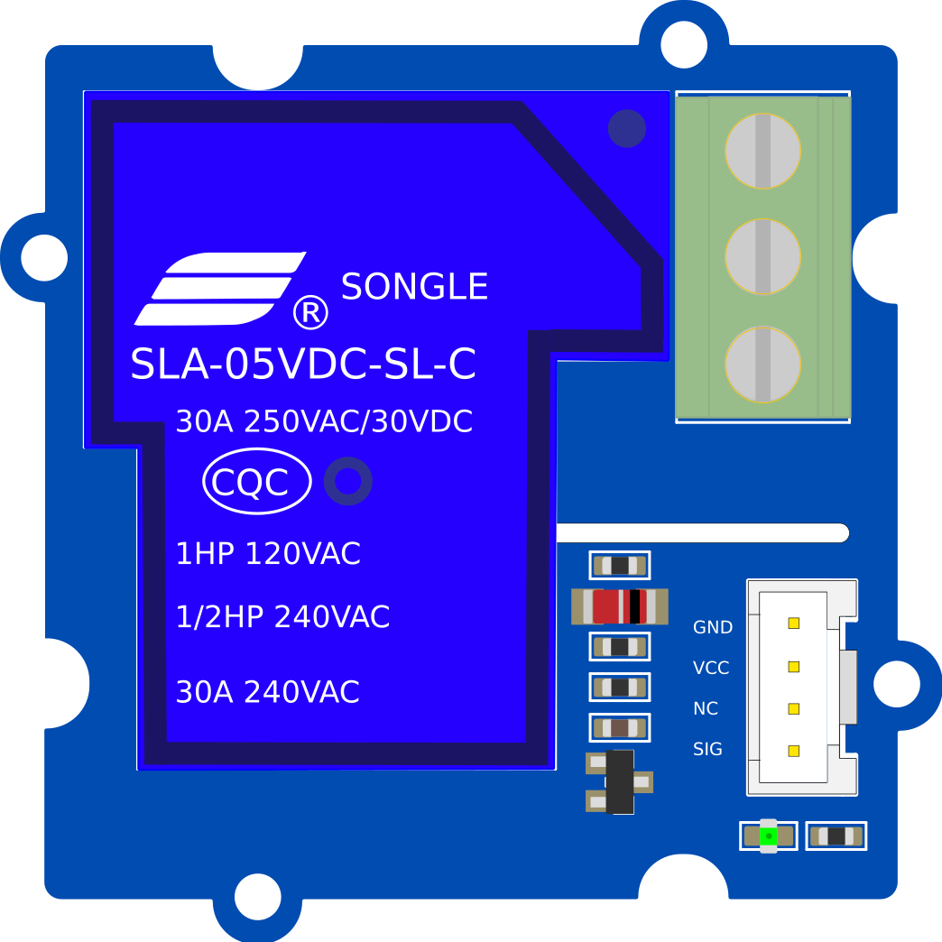
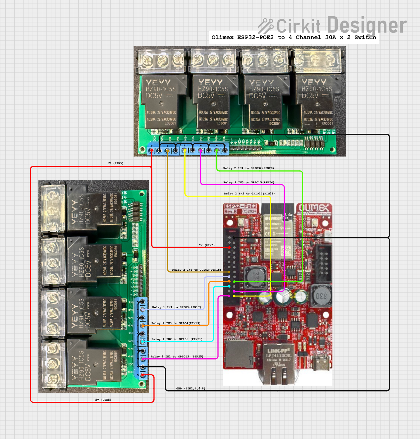
A Single Pole Double Throw (SPDT) relay is an electromechanical switch that allows a single input to toggle between two different outputs. This specific SPDT relay is rated for 30 amps, making it suitable for high-current applications. It is commonly used in automotive systems, home automation, industrial control systems, and other applications where high-power switching is required.
Explore Projects Built with SPDT Relay (30A)


Explore Projects Built with SPDT Relay (30A)
Common Applications
- Switching high-current loads such as motors, heaters, or lights.
- Automotive applications, including controlling headlights, fans, or pumps.
- Home automation systems for controlling appliances.
- Industrial equipment for switching between operational modes or power sources.
Technical Specifications
Below are the key technical details for the SPDT Relay (30A):
| Parameter | Value |
|---|---|
| Relay Type | SPDT (Single Pole Double Throw) |
| Rated Current | 30A |
| Rated Voltage | 12V DC (coil voltage) |
| Contact Voltage Rating | 250V AC / 30V DC |
| Coil Resistance | ~160Ω |
| Switching Mechanism | Electromechanical |
| Contact Material | Silver alloy |
| Dimensions | Varies by manufacturer, typically ~30x20x25mm |
Pin Configuration
The SPDT relay typically has five pins. Below is the pinout description:
| Pin Name | Description |
|---|---|
| Coil (+) | Positive terminal of the relay coil. Connect to the control voltage (e.g., 12V). |
| Coil (-) | Negative terminal of the relay coil. Connect to ground. |
| Common (COM) | The common terminal. This is the input for the circuit being switched. |
| Normally Open (NO) | The terminal that connects to COM when the relay is activated. |
| Normally Closed (NC) | The terminal that connects to COM when the relay is not activated. |
Usage Instructions
How to Use the SPDT Relay in a Circuit
- Power the Relay Coil: Connect the coil pins to a 12V DC power source. Use a transistor or relay driver circuit to control the coil if using a microcontroller.
- Connect the Load:
- Connect the input of the load to the COM pin.
- Connect one output of the load to the NO pin (for activation when the relay is energized).
- Connect the other output of the load to the NC pin (for activation when the relay is de-energized).
- Control the Relay: Use a control signal (e.g., from an Arduino or other microcontroller) to energize or de-energize the relay coil, toggling the connection between NO and NC.
Important Considerations
- Flyback Diode: Always connect a flyback diode across the relay coil to protect the control circuit from voltage spikes when the relay is turned off.
- Current Rating: Ensure the load current does not exceed the relay's 30A rating.
- Isolation: Use optocouplers or relay driver ICs for isolation when controlling the relay with sensitive electronics like microcontrollers.
- Heat Dissipation: For high-current applications, ensure proper ventilation or heat dissipation to prevent overheating.
Example: Connecting to an Arduino UNO
Below is an example of how to control the SPDT relay using an Arduino UNO:
Circuit Connections
- Connect the relay coil's positive pin to a 12V power supply.
- Connect the relay coil's negative pin to the collector of an NPN transistor (e.g., 2N2222).
- Connect the emitter of the transistor to ground.
- Connect a 1kΩ resistor between the Arduino digital pin (e.g., pin 7) and the base of the transistor.
- Place a flyback diode (e.g., 1N4007) across the relay coil, with the cathode connected to the positive pin.
Arduino Code
// Define the pin connected to the relay control circuit
const int relayPin = 7;

void setup() {
  // Set the relay pin as an output
  pinMode(relayPin, OUTPUT);
}

void loop() {
  // Activate the relay (connect COM to NO)
  digitalWrite(relayPin, HIGH);
  delay(5000); // Keep the relay on for 5 seconds

  // Deactivate the relay (connect COM to NC)
  digitalWrite(relayPin, LOW);
  delay(5000); // Keep the relay off for 5 seconds
}
Troubleshooting and FAQs
Common Issues
Relay Not Switching:
- Cause: Insufficient voltage or current to the relay coil.
- Solution: Verify that the control voltage is 12V DC and the current is sufficient to energize the coil.
Voltage Spikes Damaging the Circuit:
- Cause: Absence of a flyback diode across the relay coil.
- Solution: Install a flyback diode (e.g., 1N4007) across the coil terminals.
Overheating:
- Cause: Load current exceeds the relay's 30A rating.
- Solution: Ensure the load current is within the relay's specifications. Use a heat sink or cooling system if necessary.
Chattering or Unstable Operation:
- Cause: Insufficient or noisy control signal.
- Solution: Use a capacitor to filter noise or improve the stability of the control signal.
FAQs
Q: Can I use this relay with a 5V control signal?
A: No, the relay coil requires 12V DC to operate. You can use a transistor or relay driver circuit to interface a 5V control signal with the 12V relay.
Q: Is this relay suitable for AC loads?
A: Yes, the relay can switch AC loads up to 250V, provided the current does not exceed 30A.
Q: Can I use this relay for PWM (Pulse Width Modulation) control?
A: No, relays are not designed for high-speed switching. Use a solid-state relay or MOSFET for PWM applications.
Q: How do I know if the relay is energized?
A: Many relays include an indicator LED. If not, you can measure the voltage across the coil or listen for the clicking sound when the relay switches.