How to Use heating actuator: Examples, Pinouts, and Specs
Introduction
The alpha-5 heating actuator by Möhlenhoff is an electronic device designed to control the operation of heating systems. It is commonly used in applications such as radiators, underfloor heating, and other hydronic heating systems. The actuator functions by opening and closing valves to regulate the flow of hot water, thus controlling the temperature within a designated space. Its precise control capabilities make it an essential component in modern heating, ventilation, and air conditioning (HVAC) systems.
Explore Projects Built with heating actuator

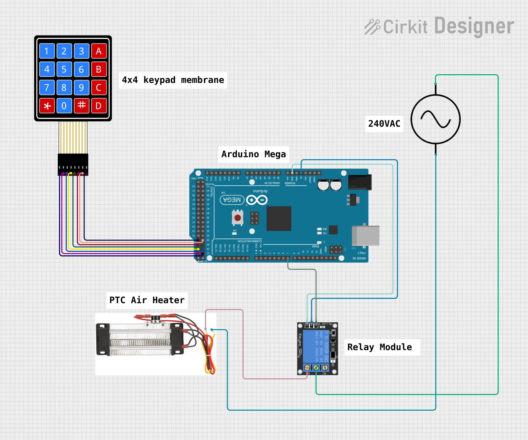
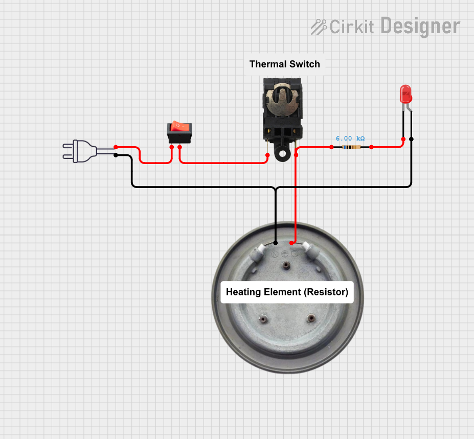
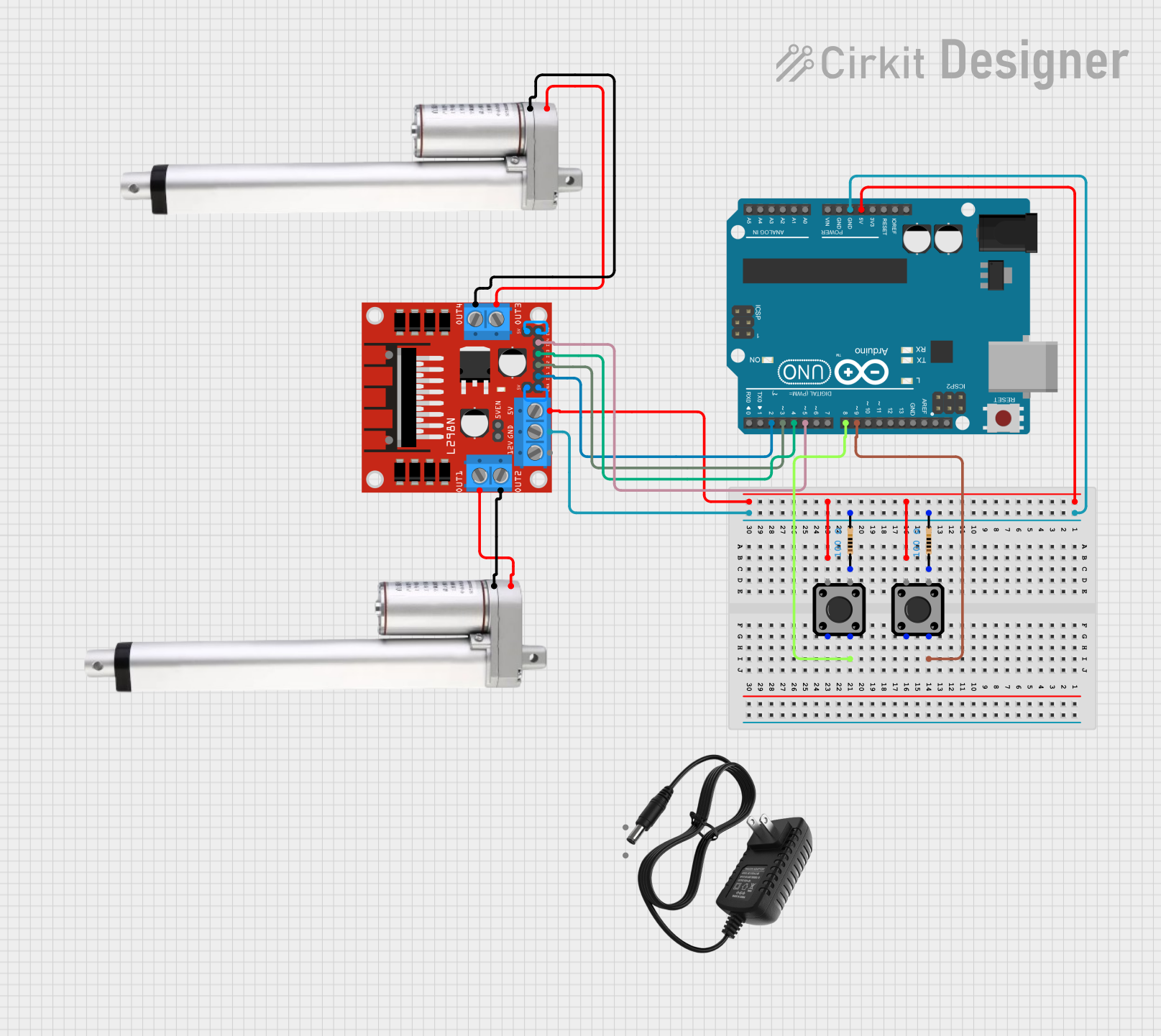
Explore Projects Built with heating actuator
Technical Specifications
General Specifications
- Manufacturer: Möhlenhoff
- Part ID: alpha-5
- Operating Voltage: 24V AC/DC
- Power Consumption: 2W
- Control Signal: 0-10V DC or PWM
- Force: 140N
- Stroke: 4mm
- Protection Class: IP54
- Ambient Temperature Range: 0°C to 50°C
Pin Configuration and Descriptions
| Pin Number | Description | Notes |
|---|---|---|
| 1 | Power Supply (+24V) | Connect to 24V power source |
| 2 | Control Signal Input | 0-10V DC or PWM signal |
| 3 | Ground | Connect to system ground |
| 4 | Feedback Signal (optional) | Provides valve position feedback |
Usage Instructions
Integration into a Circuit
- Power Supply Connection: Connect pin 1 to a 24V AC/DC power source. Ensure that the power supply can handle the current requirements of the actuator.
- Control Signal: The actuator accepts a 0-10V DC or PWM signal on pin 2 to control the valve position. This signal typically comes from a thermostat or a building management system.
- Grounding: Connect pin 3 to the system ground to complete the circuit.
- Feedback Signal: If valve position feedback is required, connect pin 4 to the input of the control system.
Important Considerations and Best Practices
- Ensure that the actuator is compatible with the valve stem of your heating system.
- Do not exceed the specified voltage and current ratings to prevent damage to the actuator.
- The actuator should be mounted in a location where it is not exposed to direct water or extreme temperatures.
- Regular maintenance checks are recommended to ensure optimal performance.
Troubleshooting and FAQs
Common Issues and Solutions
- Actuator Not Responding: Check the power supply and control signal connections. Ensure that the actuator is receiving the correct voltage and control signal.
- Noisy Operation: This could indicate a mechanical obstruction or misalignment. Inspect the valve and actuator for any signs of damage or misalignment.
- Inaccurate Temperature Control: Verify that the control signal is calibrated correctly. Adjust the signal as necessary to achieve the desired temperature.
FAQs
Q: Can the alpha-5 actuator be used with any heating system? A: The alpha-5 is designed to be versatile, but compatibility with the valve stem is crucial. Check with your system specifications or consult with a professional.
Q: What is the lifespan of the alpha-5 actuator? A: The lifespan can vary based on usage and environmental conditions. Regular maintenance can help extend the actuator's life.
Q: How do I know if the actuator is working correctly? A: The optional feedback signal can be used to monitor the valve position. Additionally, the system should maintain the set temperature if the actuator is functioning properly.
Example Arduino UNO Connection
The alpha-5 heating actuator can be controlled using an Arduino UNO for simple automation projects. Below is an example code snippet to control the actuator using a PWM signal.
// Define the control signal pin
const int controlPin = 3; // PWM output pin on Arduino UNO

void setup() {
  // Set the control pin as an output
  pinMode(controlPin, OUTPUT);
}

void loop() {
  // Example: Set the actuator to 50% open
  analogWrite(controlPin, 128); // 50% of 255 (PWM range on Arduino)

  // Wait for 10 seconds
  delay(10000);

  // Close the actuator
  analogWrite(controlPin, 0);

  // Wait for 10 seconds
  delay(10000);
}
Note: The above code is a simple demonstration. In a real-world application, the PWM signal should be generated based on temperature readings and control logic to maintain the desired temperature.
Remember to ensure that the Arduino's output voltage matches the control signal requirements of the actuator, and use appropriate level shifting or signal conditioning if necessary.