How to Use Relay Module Board 1 Channel 5V 30A With Optocoupler High Power: Examples, Pinouts, and Specs
Introduction
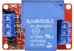
The Relay Module Board 1 Channel 5V 30A with Optocoupler High Power is a versatile electronic component designed to control high-power devices using a low-voltage signal. This module features a single relay channel capable of handling up to 30A at 5V, making it suitable for switching high-current loads such as motors, lights, and appliances. The inclusion of an optocoupler ensures electrical isolation between the control circuit and the load, enhancing safety and protecting sensitive components.
Explore Projects Built with Relay Module Board 1 Channel 5V 30A With Optocoupler High Power


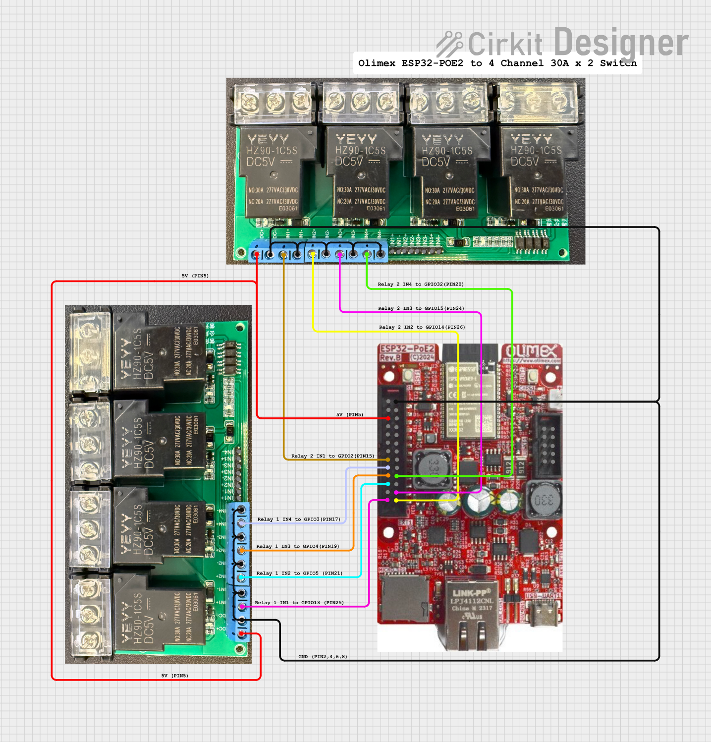

Explore Projects Built with Relay Module Board 1 Channel 5V 30A With Optocoupler High Power
Common Applications
- Home automation systems (e.g., controlling lights, fans, or appliances)
- Industrial equipment control
- Motor and pump control
- IoT projects requiring high-power switching
- Robotics and automation systems
Technical Specifications
Key Technical Details
| Parameter | Specification |
|---|---|
| Operating Voltage | 5V DC |
| Relay Channel | 1 |
| Maximum Load Current | 30A |
| Maximum Load Voltage | 250V AC / 30V DC |
| Control Signal Voltage | 3.3V to 5V |
| Isolation Method | Optocoupler |
| Trigger Type | Active Low |
| Dimensions | ~50mm x 26mm x 18mm |
| Weight | ~25g |
Pin Configuration and Descriptions
| Pin Name | Description |
|---|---|
| VCC | Connect to the 5V power supply (positive terminal). |
| GND | Connect to the ground of the power supply. |
| IN | Control signal input (active low). Connect to a microcontroller or signal. |
| COM | Common terminal of the relay switch. |
| NO | Normally Open terminal. Connect the load here for default OFF state. |
| NC | Normally Closed terminal. Connect the load here for default ON state. |
Usage Instructions
How to Use the Relay Module in a Circuit
- Power the Module: Connect the VCC pin to a 5V DC power supply and the GND pin to the ground.
- Control Signal: Connect the IN pin to a microcontroller (e.g., Arduino UNO) or a low-voltage control signal. The relay is triggered when the IN pin receives a LOW signal.
- Load Connection:
- Connect the load's live wire to the COM terminal.
- For a Normally Open (NO) configuration, connect the other load wire to the NO terminal. The load will be OFF by default and turn ON when the relay is triggered.
- For a Normally Closed (NC) configuration, connect the other load wire to the NC terminal. The load will be ON by default and turn OFF when the relay is triggered.
- Isolation: Ensure the control circuit and load circuit are electrically isolated to prevent damage to sensitive components.
Important Considerations
- Power Supply: Ensure the power supply can provide sufficient current for the relay coil and the load.
- Load Ratings: Do not exceed the relay's maximum load current (30A) or voltage (250V AC / 30V DC).
- Safety: Use proper insulation and precautions when working with high-voltage or high-current loads.
- Optocoupler Protection: The optocoupler provides isolation, but ensure the control circuit is properly grounded to avoid noise interference.
Example: Connecting to an Arduino UNO
Below is an example of how to control the relay module using an Arduino UNO:
// Example code to control a 1-channel relay module with Arduino UNO

const int relayPin = 7; // Define the pin connected to the relay module's IN pin

void setup() {
  pinMode(relayPin, OUTPUT); // Set the relay pin as an output
  digitalWrite(relayPin, HIGH); // Ensure the relay is OFF initially (active low)
}

void loop() {
  digitalWrite(relayPin, LOW); // Turn the relay ON (active low)
  delay(5000); // Keep the relay ON for 5 seconds
  digitalWrite(relayPin, HIGH); // Turn the relay OFF
  delay(5000); // Keep the relay OFF for 5 seconds
}
Notes:
- The relay is active low, meaning it turns ON when the control signal is LOW.
- Ensure the Arduino's 5V pin can supply enough current for the relay module.
Troubleshooting and FAQs
Common Issues and Solutions
Relay Not Switching:
- Cause: Insufficient control signal voltage or current.
- Solution: Ensure the control signal voltage is between 3.3V and 5V. Check the power supply for adequate current.
Load Not Turning ON/OFF:
- Cause: Incorrect wiring of the load to the relay terminals.
- Solution: Verify the load is connected to the correct terminals (COM, NO, or NC) based on the desired behavior.
Noise or Interference:
- Cause: High-power loads causing electrical noise.
- Solution: Use a snubber circuit or flyback diode across the load to suppress noise.
Relay Stuck in ON/OFF State:
- Cause: Exceeding the relay's maximum current or voltage ratings.
- Solution: Ensure the load does not exceed 30A or 250V AC / 30V DC. Replace the relay if damaged.
FAQs
Q: Can I use this relay module with a 3.3V microcontroller?
A: Yes, the relay module can be triggered with a 3.3V control signal, but ensure the VCC pin is powered with 5V.
Q: Is the relay suitable for DC loads?
A: Yes, the relay can handle DC loads up to 30V at 30A.
Q: Can I control multiple relays with one microcontroller?
A: Yes, as long as each relay has its own control pin and the microcontroller can supply sufficient current.
Q: Does the module include reverse polarity protection?
A: No, ensure correct polarity when connecting the power supply to avoid damage.