How to Use Limit Switch: Examples, Pinouts, and Specs
Introduction
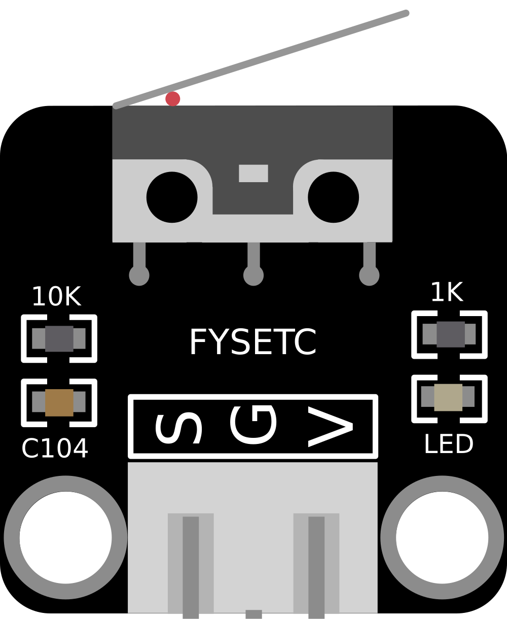
A limit switch is an electromechanical device designed to detect the presence or absence of an object or to monitor the limits of motion of a part. It is commonly used in industrial control systems and various mechanical applications to provide a control signal for the movement of machinery, such as stopping or starting an operation when an object reaches a predetermined position.
Explore Projects Built with Limit Switch
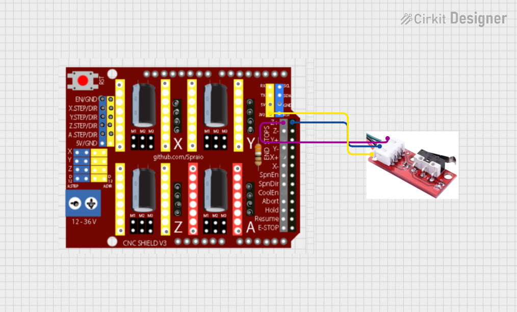
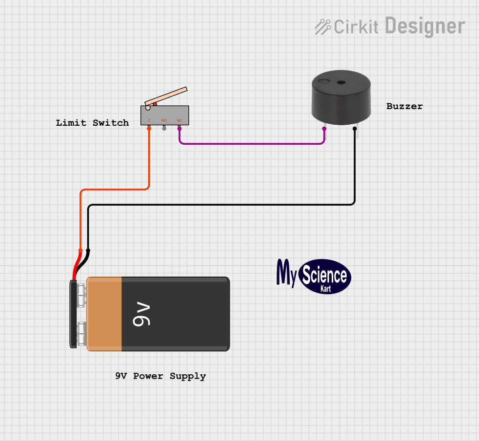
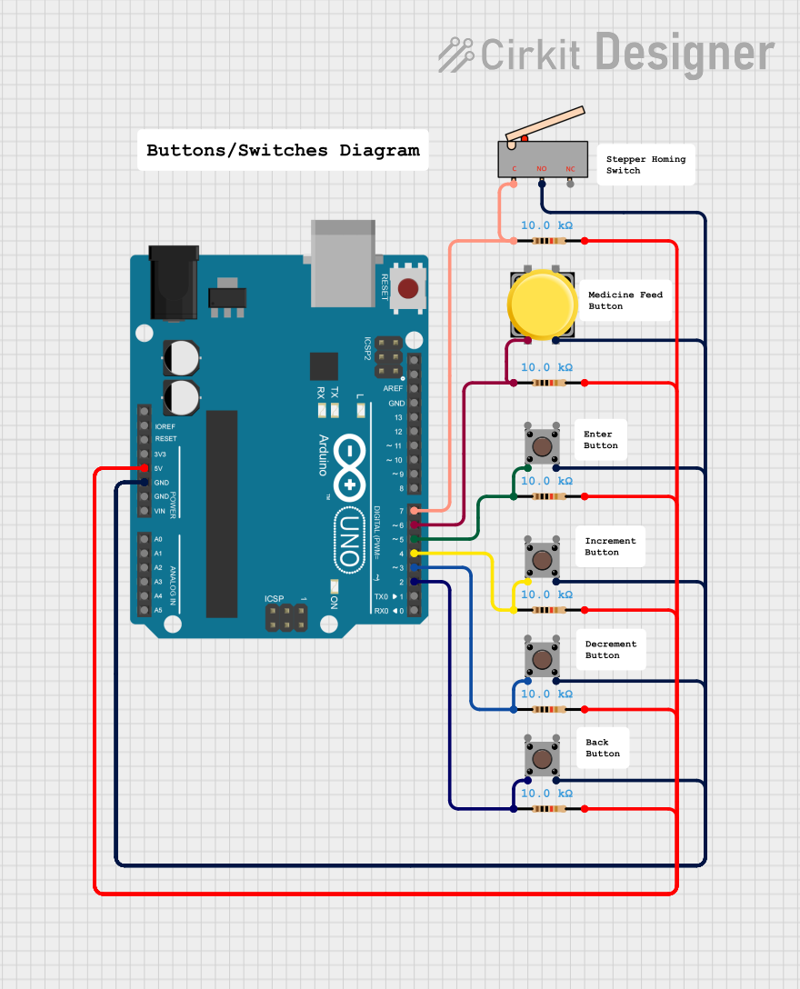

Explore Projects Built with Limit Switch
Common Applications and Use Cases
- Industrial Automation: To control the movement of mechanical parts in automated assembly lines.
- Safety Mechanisms: To prevent machinery from moving beyond safe operational limits.
- Position Sensing: In elevators, gates, and doors to detect the open or closed state.
- End-of-Travel Detection: In CNC machines to establish reference points for machine components.
Technical Specifications
Key Technical Details
- Rated Voltage: Typically ranges from 5V to 250V, depending on the model.
- Rated Current: Can vary from a few milliamps to several amps.
- Contact Configuration: Normally Open (NO), Normally Closed (NC), or both.
- Mechanical Life: Often rated for millions of actuations.
- Operating Force: The force required to activate the switch varies by design.
Pin Configuration and Descriptions
| Pin Number | Description | Notes |
|---|---|---|
| 1 | Common (COM) | Connects to the power supply or ground |
| 2 | Normally Closed (NC) | Closed when the switch is not activated |
| 3 | Normally Open (NO) | Closed when the switch is activated |
Usage Instructions
How to Use the Limit Switch in a Circuit
- Identify the Pins: Determine the COM, NO, and NC pins on the limit switch.
- Wiring: Connect the COM pin to one side of the power supply. Connect the NO or NC pin to the load (e.g., relay, LED, motor controller) depending on the desired behavior.
- Mounting: Secure the limit switch in a position where the moving object will engage the actuator of the switch at the desired point.
- Testing: Manually activate the switch to ensure it operates the connected load as expected.
Important Considerations and Best Practices
- Debouncing: Limit switches may require debouncing, either through hardware or software, to prevent false triggering from mechanical vibrations.
- Load Ratings: Ensure the switch's voltage and current ratings are suitable for the load it will control.
- Environmental Factors: Choose a limit switch with appropriate protection for the operating environment (e.g., dust, moisture, temperature).
Example Code for Arduino UNO
// Define the pin connected to the limit switch
const int limitSwitchPin = 2;

void setup() {
  pinMode(limitSwitchPin, INPUT_PULLUP); // Set the limit switch pin as input with internal pull-up
  Serial.begin(9600);                    // Initialize serial communication
}

void loop() {
  // Read the state of the limit switch
  int switchState = digitalRead(limitSwitchPin);

  // Check if the switch is pressed (assuming NO configuration)
  if (switchState == LOW) {
    // The limit switch is activated
    Serial.println("Limit switch is activated.");
    // Add control logic here (e.g., stop a motor)
  } else {
    // The limit switch is not activated
    Serial.println("Limit switch is not activated.");
    // Add control logic here (e.g., run a motor)
  }

  delay(100); // Debounce delay
}
Troubleshooting and FAQs
Common Issues Users Might Face
- Switch Does Not Activate: Ensure the object properly engages the actuator and check wiring connections.
- Intermittent Operation: Check for mechanical wear or loose connections. Consider implementing a debounce circuit or software debouncing.
Solutions and Tips for Troubleshooting
- Testing Continuity: Use a multimeter to test the continuity of the switch in both the activated and non-activated states.
- Adjusting Actuator: Some limit switches have adjustable actuators. Ensure it is set to the correct position for reliable operation.
FAQs
Q: Can I use a limit switch with a microcontroller like an Arduino? A: Yes, limit switches can be easily interfaced with microcontrollers using digital input pins.
Q: What is the difference between NO and NC configurations? A: NO (Normally Open) means the switch is open (non-conductive) when not pressed, and NC (Normally Closed) means the switch is closed (conductive) when not pressed.
Q: How do I know if my limit switch requires debouncing? A: If you observe erratic behavior or multiple signals from a single actuation, debouncing may be necessary.