Cirkit Designer Logo
Cirkit Designer
Your all-in-one circuit design IDE
Home / 
Component Documentation

How to Use HC12 ANTENNA: Examples, Pinouts, and Specs

Image of HC12 ANTENNA
Cirkit Designer LogoDesign with HC12 ANTENNA in Cirkit Designer

Introduction

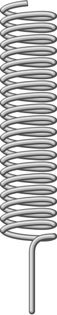
The HC12 Antenna is a high-performance antenna specifically designed for use with HC-12 wireless communication modules. It enhances the signal range and quality, making it ideal for long-distance data transmission. This antenna is a critical component for applications requiring reliable wireless communication over extended distances.

Explore Projects Built with HC12 ANTENNA

Use Cirkit Designer to design, explore, and prototype these projects online. Some projects support real-time simulation. Click "Open Project" to start designing instantly!
Satellite Compass and Network-Integrated GPS Data Processing System
Image of GPS 시스템 측정 구성도_241016: A project utilizing HC12 ANTENNA in a practical application
This circuit comprises a satellite compass, a mini PC, two GPS antennas, power supplies, a network switch, media converters, and an atomic rubidium clock. The satellite compass is powered by a triple output DC power supply and interfaces with an RS232 splitter for 1PPS signals. The mini PCs are connected to the USRP B200 devices via USB for data and power, and to media converters via Ethernet, which in turn connect to a network switch using fiber optic links. The antennas are connected to the USRP B200s through RF directional couplers, and the atomic clock provides a 1PPS input to the RS232 splitter.
Cirkit Designer LogoOpen Project in Cirkit Designer
Satellite-Based Timing and Navigation System with SDR and Atomic Clock Synchronization
Image of GPS 시스템 측정 구성도_Confirm: A project utilizing HC12 ANTENNA in a practical application
This circuit appears to be a complex system involving power supply management, GPS and timing synchronization, and data communication. It includes a SI-TEX G1 Satellite Compass for GPS data, an XHTF1021 Atomic Rubidium Clock for precise timing, and Ettus USRP B200 units for software-defined radio communication. Power is supplied through various SMPS units and distributed via terminal blocks and DC jacks. Data communication is facilitated by Beelink MINI S12 N95 computers, RS232 splitters, and a 1000BASE-T Media Converter for network connectivity. RF Directional Couplers are used to interface antennas with the USRP units, and the entire system is likely contained within cases for protection and organization.
Cirkit Designer LogoOpen Project in Cirkit Designer
Raspberry Pi Pico-Based Navigation Assistant with Bluetooth and GPS
Image of sat_dish: compass example: A project utilizing HC12 ANTENNA in a practical application
This circuit features a Raspberry Pi Pico microcontroller interfaced with an HC-05 Bluetooth module for wireless communication, an HMC5883L compass module for magnetic field measurement, and a GPS NEO 6M module for location tracking. The Pico is configured to communicate with the HC-05 via serial connection (TX/RX), with the compass module via I2C (SCL/SDA), and with the GPS module via serial (TX/RX). Common power (VCC) and ground (GND) lines are shared among all modules, indicating a unified power system.
Cirkit Designer LogoOpen Project in Cirkit Designer
Battery-Powered nRF52840 and HT-RA62 Communication Module
Image of NRF52840+HT-RA62: A project utilizing HC12 ANTENNA in a practical application
This circuit is a wireless communication system powered by a 18650 Li-ion battery, featuring an nRF52840 ProMicro microcontroller and an HT-RA62 transceiver module. The nRF52840 handles the control logic and interfaces with the HT-RA62 for data transmission, while the battery provides the necessary power for the entire setup.
Cirkit Designer LogoOpen Project in Cirkit Designer

Explore Projects Built with HC12 ANTENNA

Use Cirkit Designer to design, explore, and prototype these projects online. Some projects support real-time simulation. Click "Open Project" to start designing instantly!
Image of GPS 시스템 측정 구성도_241016: A project utilizing HC12 ANTENNA in a practical application
Satellite Compass and Network-Integrated GPS Data Processing System
This circuit comprises a satellite compass, a mini PC, two GPS antennas, power supplies, a network switch, media converters, and an atomic rubidium clock. The satellite compass is powered by a triple output DC power supply and interfaces with an RS232 splitter for 1PPS signals. The mini PCs are connected to the USRP B200 devices via USB for data and power, and to media converters via Ethernet, which in turn connect to a network switch using fiber optic links. The antennas are connected to the USRP B200s through RF directional couplers, and the atomic clock provides a 1PPS input to the RS232 splitter.
Cirkit Designer LogoOpen Project in Cirkit Designer
Image of GPS 시스템 측정 구성도_Confirm: A project utilizing HC12 ANTENNA in a practical application
Satellite-Based Timing and Navigation System with SDR and Atomic Clock Synchronization
This circuit appears to be a complex system involving power supply management, GPS and timing synchronization, and data communication. It includes a SI-TEX G1 Satellite Compass for GPS data, an XHTF1021 Atomic Rubidium Clock for precise timing, and Ettus USRP B200 units for software-defined radio communication. Power is supplied through various SMPS units and distributed via terminal blocks and DC jacks. Data communication is facilitated by Beelink MINI S12 N95 computers, RS232 splitters, and a 1000BASE-T Media Converter for network connectivity. RF Directional Couplers are used to interface antennas with the USRP units, and the entire system is likely contained within cases for protection and organization.
Cirkit Designer LogoOpen Project in Cirkit Designer
Image of sat_dish: compass example: A project utilizing HC12 ANTENNA in a practical application
Raspberry Pi Pico-Based Navigation Assistant with Bluetooth and GPS
This circuit features a Raspberry Pi Pico microcontroller interfaced with an HC-05 Bluetooth module for wireless communication, an HMC5883L compass module for magnetic field measurement, and a GPS NEO 6M module for location tracking. The Pico is configured to communicate with the HC-05 via serial connection (TX/RX), with the compass module via I2C (SCL/SDA), and with the GPS module via serial (TX/RX). Common power (VCC) and ground (GND) lines are shared among all modules, indicating a unified power system.
Cirkit Designer LogoOpen Project in Cirkit Designer
Image of NRF52840+HT-RA62: A project utilizing HC12 ANTENNA in a practical application
Battery-Powered nRF52840 and HT-RA62 Communication Module
This circuit is a wireless communication system powered by a 18650 Li-ion battery, featuring an nRF52840 ProMicro microcontroller and an HT-RA62 transceiver module. The nRF52840 handles the control logic and interfaces with the HT-RA62 for data transmission, while the battery provides the necessary power for the entire setup.
Cirkit Designer LogoOpen Project in Cirkit Designer

Common Applications and Use Cases

  • Wireless sensor networks
  • Remote monitoring and control systems
  • Internet of Things (IoT) devices
  • Home automation systems
  • Robotics and drone communication
  • Industrial automation

Technical Specifications

The HC12 Antenna is optimized for use with the HC-12 module and operates within the 433 MHz frequency band. Below are the key technical details:

Key Specifications

Parameter Value
Frequency Range 433 MHz
Impedance 50 Ω
Gain 3 dBi
Connector Type SMA Male
Polarization Vertical
Length ~11 cm
Material Stainless steel and plastic
Operating Temperature -40°C to +85°C

Pin Configuration and Descriptions

The HC12 Antenna does not have pins but connects to the HC-12 module via an SMA connector. Ensure the SMA connector on the HC-12 module matches the antenna's SMA male connector.

Usage Instructions

How to Use the HC12 Antenna in a Circuit

  1. Connect the Antenna to the HC-12 Module:

    • Attach the SMA male connector of the antenna to the SMA female connector on the HC-12 module. Ensure a secure and tight connection to avoid signal loss.
  2. Position the Antenna:

    • Place the antenna in a vertical orientation for optimal signal strength.
    • Avoid placing the antenna near metal objects or inside enclosures that may block or interfere with the signal.
  3. Power the HC-12 Module:

    • Connect the HC-12 module to your microcontroller or power source as per the HC-12 module's specifications.
    • Ensure the module is configured correctly for the desired communication settings (e.g., baud rate, channel).
  4. Test the Communication:

    • Use a pair of HC-12 modules with antennas to test the wireless communication range and quality.
    • Adjust the antenna position if necessary to improve signal strength.

Important Considerations and Best Practices

  • Antenna Placement: For maximum range, position the antenna in an open area, away from obstructions and interference sources.
  • Signal Interference: Avoid using the antenna in environments with high RF noise or overlapping frequency bands.
  • Connector Care: Handle the SMA connector carefully to prevent damage or wear, which could degrade signal quality.
  • Compatibility: Ensure the antenna is compatible with the HC-12 module and operates within the same frequency range (433 MHz).

Example: Using HC12 Antenna with Arduino UNO

Below is an example of how to use the HC12 module with the HC12 Antenna and an Arduino UNO for wireless communication:

#include <SoftwareSerial.h>

// Define RX and TX pins for HC-12 communication
SoftwareSerial HC12(10, 11); // HC-12 TX Pin to Arduino pin 10, RX Pin to pin 11

void setup() {
  Serial.begin(9600);       // Start serial communication with the PC
  HC12.begin(9600);         // Start serial communication with the HC-12 module
  Serial.println("HC-12 Antenna Test");
}

void loop() {
  if (HC12.available()) {
    // Read data from HC-12 and send it to the Serial Monitor
    Serial.write(HC12.read());
  }
  if (Serial.available()) {
    // Read data from Serial Monitor and send it to HC-12
    HC12.write(Serial.read());
  }
}

Note: Ensure the HC-12 module is properly connected to the Arduino UNO, and the antenna is securely attached to the HC-12 module.

Troubleshooting and FAQs

Common Issues and Solutions

  1. Weak Signal or Short Range:

    • Cause: Poor antenna placement or obstructions.
    • Solution: Reposition the antenna in a vertical orientation and move it to an open area.
  2. No Communication Between Modules:

    • Cause: Incorrect HC-12 configuration or damaged antenna.
    • Solution: Verify the HC-12 module settings (e.g., baud rate, channel) and check the antenna connection.
  3. Intermittent Signal Loss:

    • Cause: RF interference or loose SMA connector.
    • Solution: Minimize interference sources and ensure the SMA connector is tightly secured.
  4. Antenna Not Fitting the HC-12 Module:

    • Cause: Incompatible connector type.
    • Solution: Confirm that the HC-12 module has an SMA female connector compatible with the antenna.

FAQs

Q1: Can I use the HC12 Antenna with other modules?
A1: Yes, as long as the module operates at 433 MHz and has a compatible SMA connector.

Q2: What is the maximum range of the HC12 Antenna?
A2: The range depends on environmental factors and the HC-12 module's power settings. In open areas, it can achieve up to 1 km or more.

Q3: Can I extend the antenna cable?
A3: Yes, but using a longer cable may introduce signal loss. Use high-quality, low-loss cables if extension is necessary.

Q4: Is the antenna waterproof?
A4: The HC12 Antenna is not fully waterproof. Use protective enclosures if deploying it in outdoor environments.