How to Use TTL Serial JPEG Camera: Examples, Pinouts, and Specs
Introduction
The TTL Serial JPEG Camera is a compact and easy-to-use camera module designed for microcontroller projects. It captures high-quality images in JPEG format and transmits them over a TTL serial interface, making it ideal for embedded systems. Common applications include security systems, robotics, environmental monitoring, and DIY projects where visual data capture is required.
Explore Projects Built with TTL Serial JPEG Camera
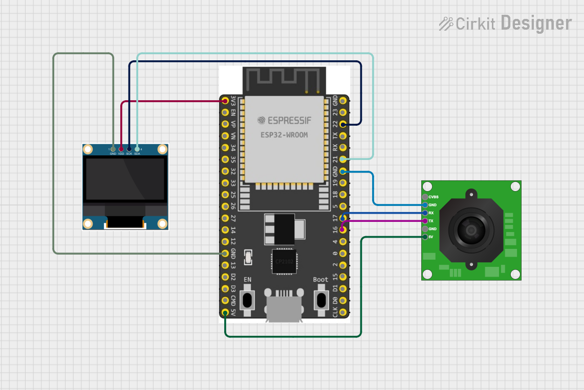
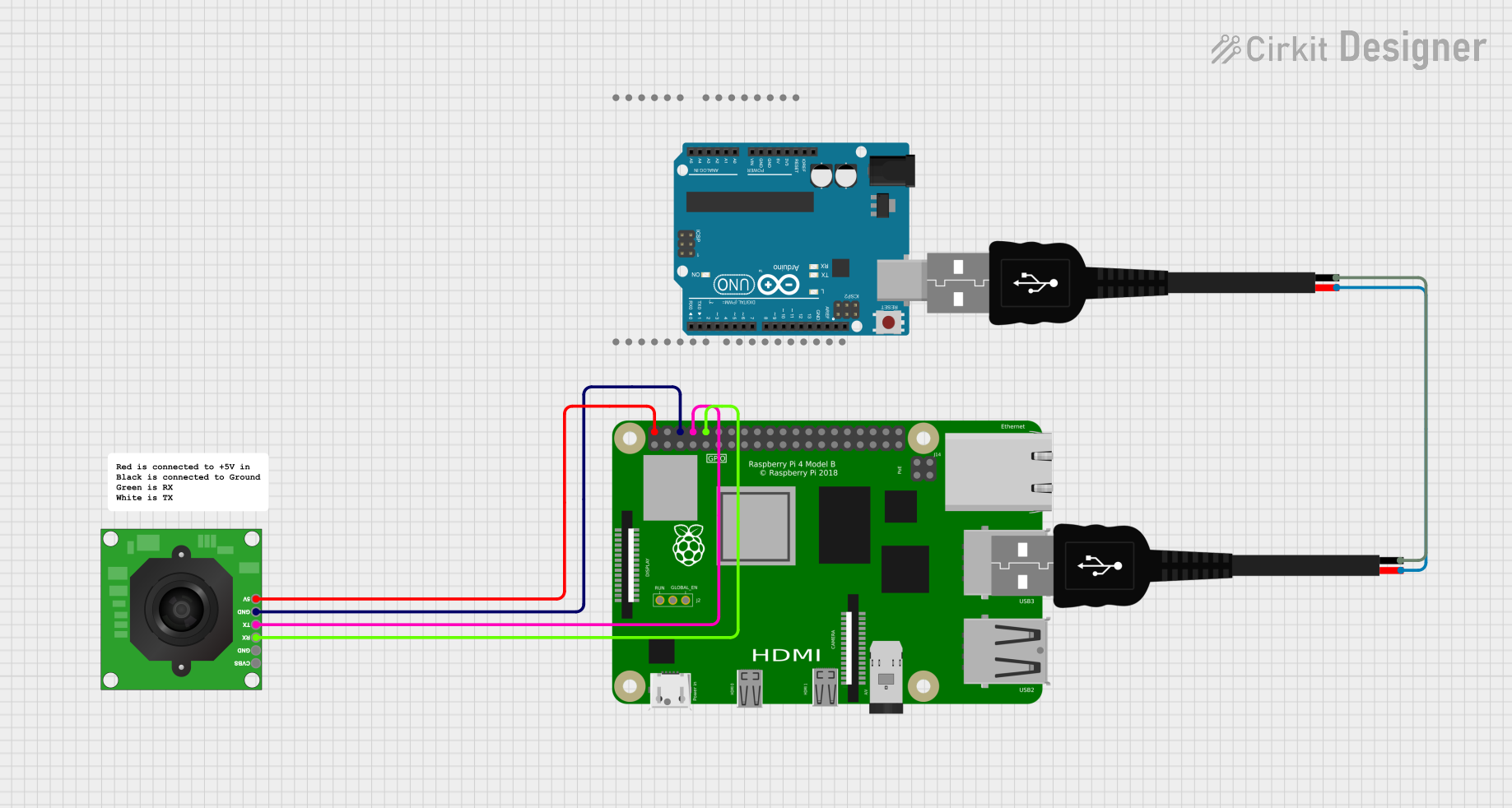
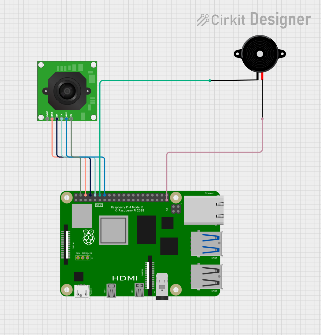
Explore Projects Built with TTL Serial JPEG Camera
Technical Specifications
General Features
- Image Sensor: CMOS
- Resolution: Configurable (e.g., 640x480, 320x240)
- Output Format: JPEG
- Interface: TTL Serial (5V logic level)
- Baud Rate: Configurable (default 38400 bps)
- Power Supply: 3.3V to 5V DC
- Current Consumption: ~60mA (active), ~20mA (idle)
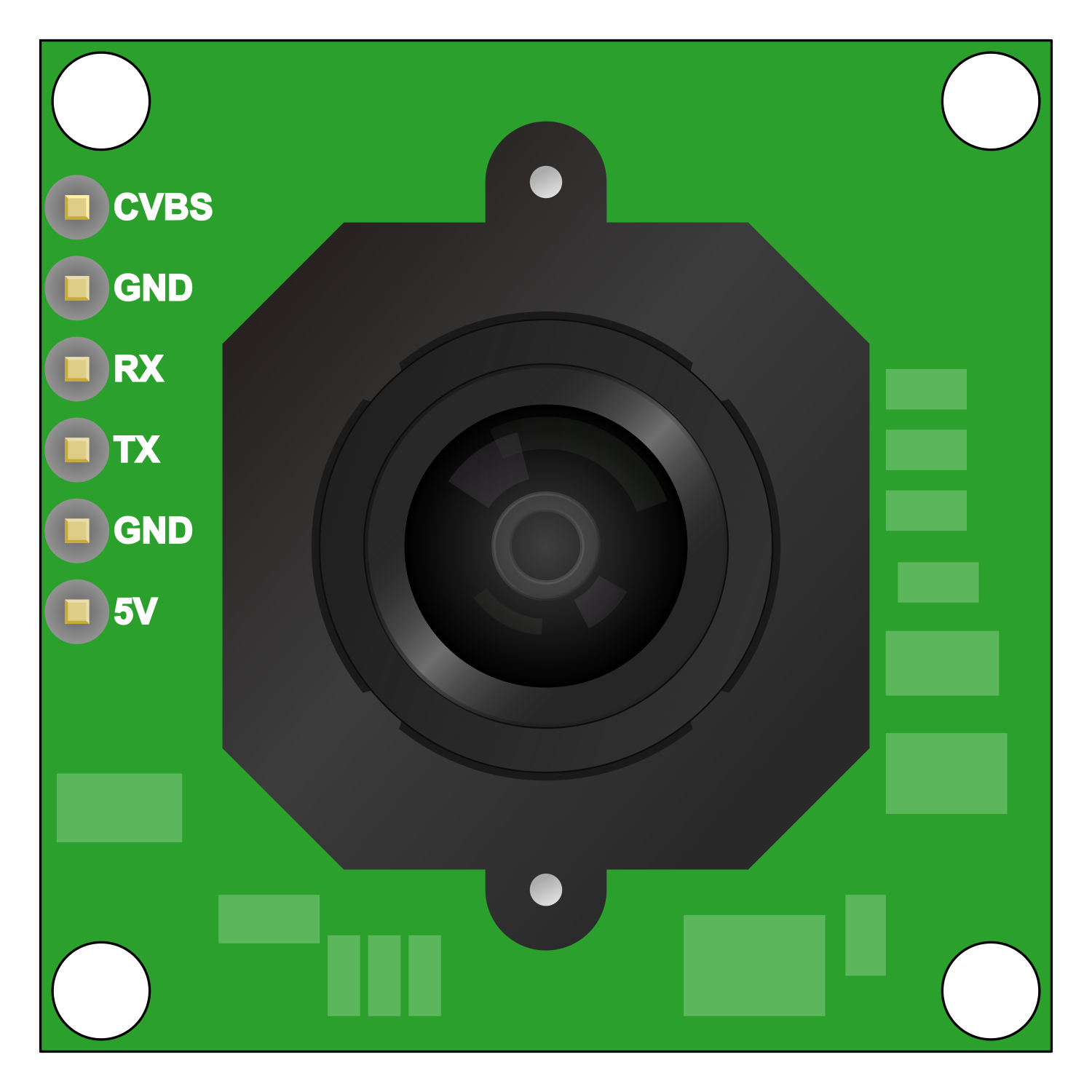
Pin Configuration and Descriptions
| Pin Number | Name | Description |
|---|---|---|
| 1 | VCC | Power supply (3.3V to 5V DC) |
| 2 | GND | Ground connection |
| 3 | RX | TTL Serial Receive Pin |
| 4 | TX | TTL Serial Transmit Pin |
| 5 | RESET | Reset pin (active low) |
Usage Instructions
Connecting to a Circuit
- Connect the VCC pin to a 3.3V or 5V power supply.
- Connect the GND pin to the ground of the power supply.
- Connect the RX pin to the TX pin of the microcontroller.
- Connect the TX pin to the RX pin of the microcontroller.
- (Optional) Connect the RESET pin to a digital pin on the microcontroller for software reset capability.
Best Practices
- Ensure that the power supply is stable and within the specified voltage range.
- Use a level shifter if the microcontroller operates at a different logic level than 5V.
- Avoid exposing the camera lens to direct sunlight or strong light sources that may damage the sensor.
- Implement proper error handling in your code to deal with communication timeouts and data corruption.
Example Code for Arduino UNO
#include <SoftwareSerial.h>

// RX, TX pins for connecting to the camera
SoftwareSerial cameraSerial(10, 11); // RX, TX

void setup() {
  // Start the serial communication
  Serial.begin(9600);
  cameraSerial.begin(38400); // Default baud rate of the camera
  Serial.println("Camera module initialized");
}

void loop() {
  // Code to capture and retrieve an image from the camera
  // This is a placeholder for actual implementation
}
Troubleshooting and FAQs
Common Issues
- Image data is corrupted: Ensure the baud rate is correctly set and matches the camera's configuration.
- No response from the camera: Check all connections, including power supply and serial connections. Ensure the camera is powered on.
- Poor image quality: Adjust the focus of the camera lens, check for obstructions, or consider external lighting conditions.
FAQs
Q: How do I change the resolution of the camera? A: Send the appropriate command over the serial interface to the camera to change the resolution settings.
Q: Can I use this camera with a 3.3V microcontroller? A: Yes, but ensure that the logic levels are compatible, or use a level shifter if necessary.
Q: How can I reset the camera? A: You can reset the camera by pulling the RESET pin low or by sending a reset command via the serial interface.
Q: How long does it take to capture an image? A: The capture time can vary based on resolution and lighting conditions, but it typically takes a few hundred milliseconds.
For more detailed troubleshooting, refer to the manufacturer's datasheet and technical support forums.