How to Use GY- BNO085 AR VR IMU: Examples, Pinouts, and Specs
Introduction
The GY-BNO085 is an advanced Inertial Measurement Unit (IMU) that integrates a 3-axis accelerometer, 3-axis gyroscope, and 3-axis magnetometer. It features a built-in sensor fusion algorithm to deliver precise orientation data, making it ideal for motion tracking applications. This module is widely used in augmented reality (AR), virtual reality (VR), robotics, drones, and other systems requiring accurate spatial awareness.
Explore Projects Built with GY- BNO085 AR VR IMU


Explore Projects Built with GY- BNO085 AR VR IMU
Common Applications:
- AR/VR headsets for motion tracking
- Robotics for navigation and control
- Drones for stabilization and orientation
- Gaming controllers and motion-based input devices
- Wearable devices for activity tracking
Technical Specifications
The GY-BNO085 module is designed for high-performance motion sensing and orientation tracking. Below are its key technical details:
Key Specifications:
| Parameter | Value |
|---|---|
| Operating Voltage | 3.3V (logic level) |
| Power Supply Voltage | 3.3V to 5V |
| Communication Protocols | I2C, SPI, UART |
| Accelerometer Range | ±2g, ±4g, ±8g, ±16g |
| Gyroscope Range | ±125°/s, ±250°/s, ±500°/s, ±2000°/s |
| Magnetometer Range | ±4900 µT |
| Orientation Output | Quaternion, Euler angles |
| Operating Temperature | -40°C to +85°C |
| Dimensions | 15mm x 15mm |
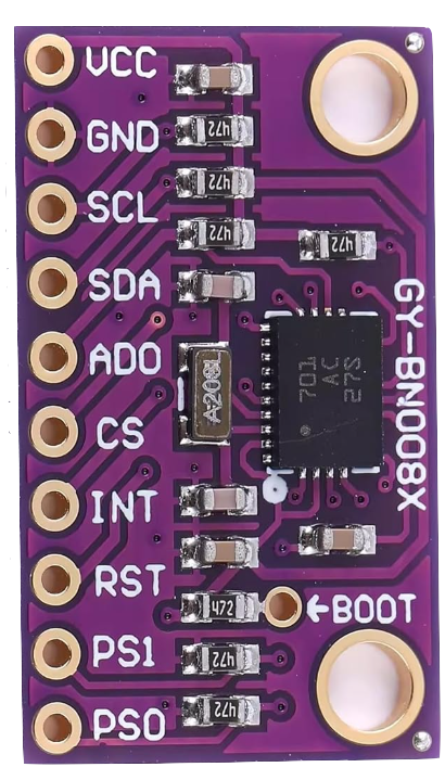
Pin Configuration:
The GY-BNO085 module has the following pinout:
| Pin Name | Description |
|---|---|
| VIN | Power input (3.3V to 5V) |
| GND | Ground |
| SCL | I2C clock line |
| SDA | I2C data line |
| CS | Chip select for SPI communication |
| SDO | SPI data output |
| INT | Interrupt pin for data ready signal |
| RST | Reset pin |
Usage Instructions
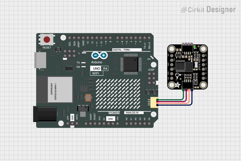
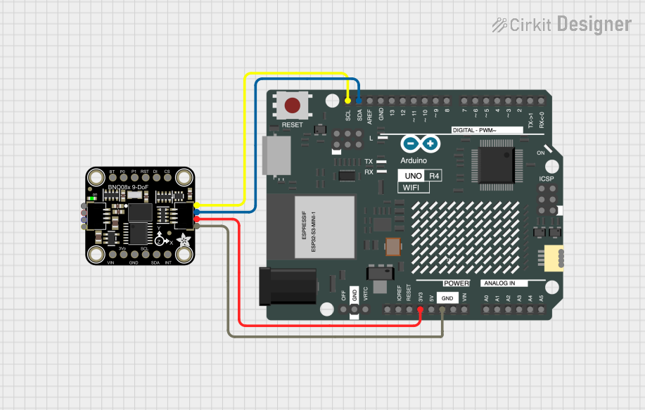
The GY-BNO085 can be interfaced with microcontrollers like the Arduino UNO using I2C, SPI, or UART communication. Below are the steps to use the module in a circuit:
Connecting the GY-BNO085 to an Arduino UNO (I2C Mode):
- Power the Module: Connect the
VINpin to the Arduino's5Vpin and theGNDpin to the Arduino'sGND. - I2C Communication: Connect the
SCLpin to the Arduino'sA5pin and theSDApin to the Arduino'sA4pin. - Optional Connections: The
INTpin can be connected to a digital pin on the Arduino to detect data-ready interrupts.
Sample Arduino Code:
The following code demonstrates how to read orientation data from the GY-BNO085 using I2C:
#include <Wire.h>
#include <Adafruit_Sensor.h>
#include <Adafruit_BNO08x.h>

// Create an instance of the BNO08x sensor
Adafruit_BNO08x bno = Adafruit_BNO08x();

// Define the I2C address of the sensor
#define BNO08X_I2C_ADDRESS 0x4A

void setup() {
  Serial.begin(115200); // Initialize serial communication
  Wire.begin();         // Initialize I2C communication

  // Initialize the BNO08x sensor
  if (!bno.begin_I2C(BNO08X_I2C_ADDRESS)) {
    Serial.println("Failed to initialize BNO08x! Check connections.");
    while (1);
  }
  Serial.println("BNO08x initialized successfully!");

  // Configure the sensor to output rotation vector data
  if (!bno.enableReport(BNO08X_REPORT_ROTATION_VECTOR)) {
    Serial.println("Failed to enable rotation vector report!");
    while (1);
  }
}

void loop() {
  // Check if new data is available
  if (bno.getEvent()) {
    // Retrieve the rotation vector data
    sensors_event_t event;
    bno.getEvent(&event);

    // Print the quaternion data to the serial monitor
    Serial.print("Quaternion: ");
    Serial.print("W: "); Serial.print(event.orientation.w, 4);
    Serial.print(", X: "); Serial.print(event.orientation.x, 4);
    Serial.print(", Y: "); Serial.print(event.orientation.y, 4);
    Serial.print(", Z: "); Serial.println(event.orientation.z, 4);
  }

  delay(100); // Delay to avoid flooding the serial monitor
}
Important Considerations:
- Ensure the module is powered with the correct voltage (3.3V to 5V).
- Use appropriate pull-up resistors (typically 4.7kΩ) on the I2C lines if they are not already present on the module.
- Avoid placing the module near magnetic or metallic objects that could interfere with the magnetometer.
Troubleshooting and FAQs
Common Issues:
Sensor Not Detected:
- Cause: Incorrect wiring or I2C address mismatch.
- Solution: Double-check the connections and ensure the correct I2C address is used in the code.
Inaccurate Orientation Data:
- Cause: Magnetic interference or improper calibration.
- Solution: Perform a calibration routine and avoid placing the module near magnetic sources.
No Data Output:
- Cause: Interrupt pin not connected or incorrect communication protocol.
- Solution: Ensure the
INTpin is connected (if required) and verify the selected communication protocol.
FAQs:
Q1: Can the GY-BNO085 be used with 5V logic microcontrollers?
A1: Yes, the module is compatible with 5V logic levels, but ensure the VIN pin is supplied with 5V.
Q2: How do I calibrate the sensor?
A2: Calibration can be performed by moving the sensor in a figure-eight pattern to calibrate the magnetometer. Refer to the sensor's datasheet for detailed calibration instructions.
Q3: What is the default I2C address of the GY-BNO085?
A3: The default I2C address is 0x4A. Some modules may allow changing the address via solder jumpers.
By following this documentation, you can effectively integrate the GY-BNO085 into your projects for precise motion tracking and orientation sensing.