How to Use Raspberry Pi Zero 2 W: Examples, Pinouts, and Specs
Introduction
The Raspberry Pi Zero 2 W is a compact, low-cost single-board computer developed by Raspberry Pi. It is designed to provide a powerful yet affordable platform for a wide range of applications, including Internet of Things (IoT) projects, lightweight computing tasks, and educational purposes. With its built-in wireless capabilities, the Zero 2 W is an excellent choice for projects requiring connectivity in a small form factor.
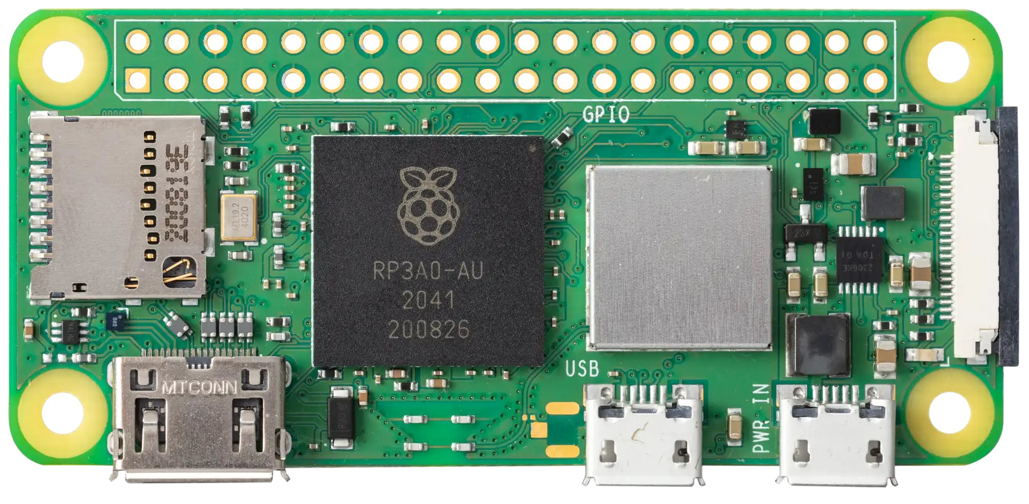
Explore Projects Built with Raspberry Pi Zero 2 W
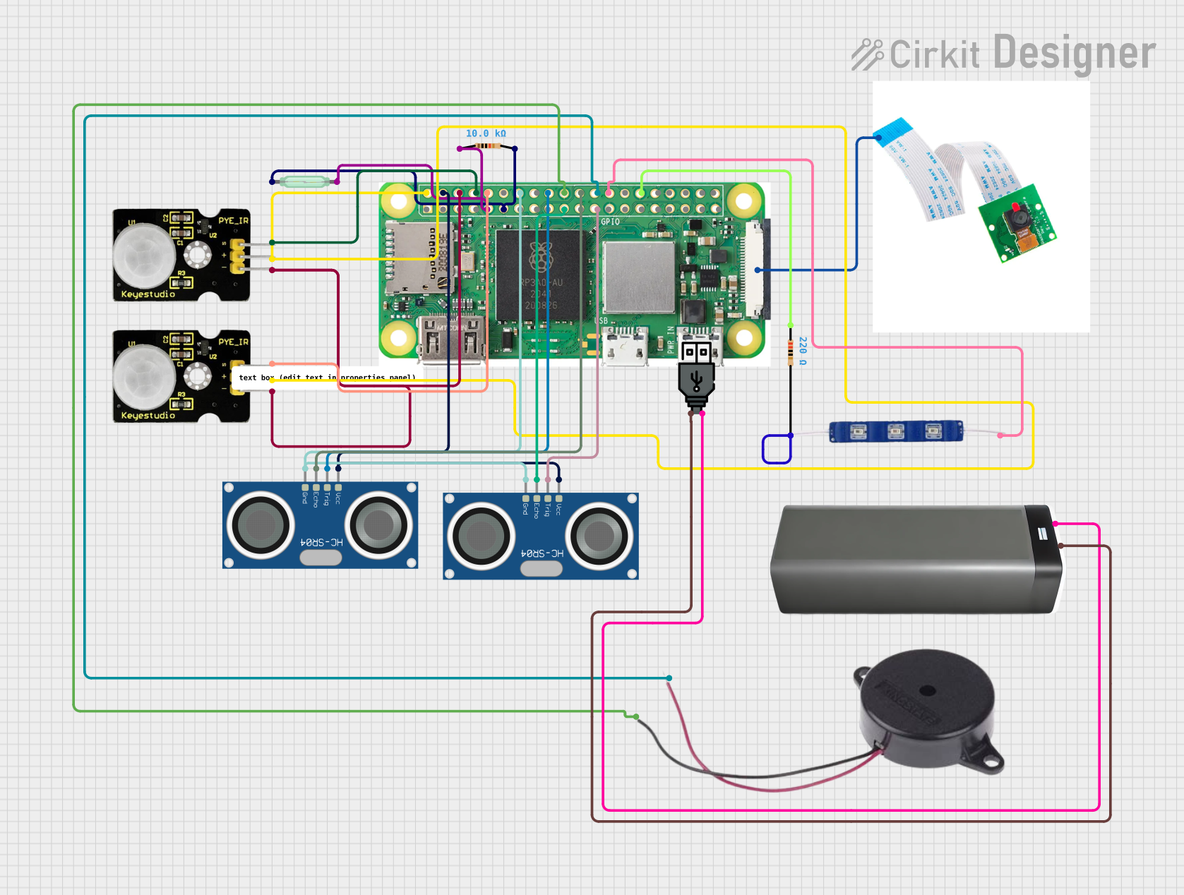
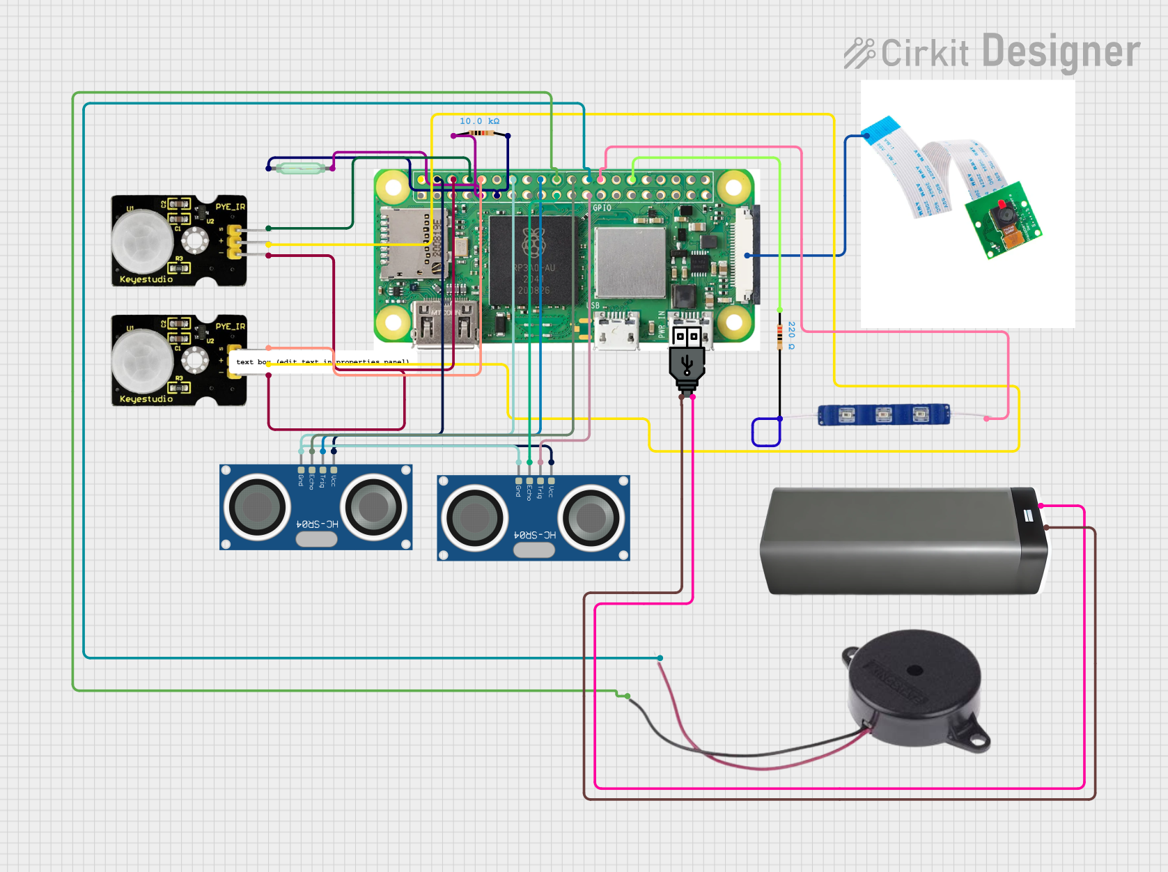
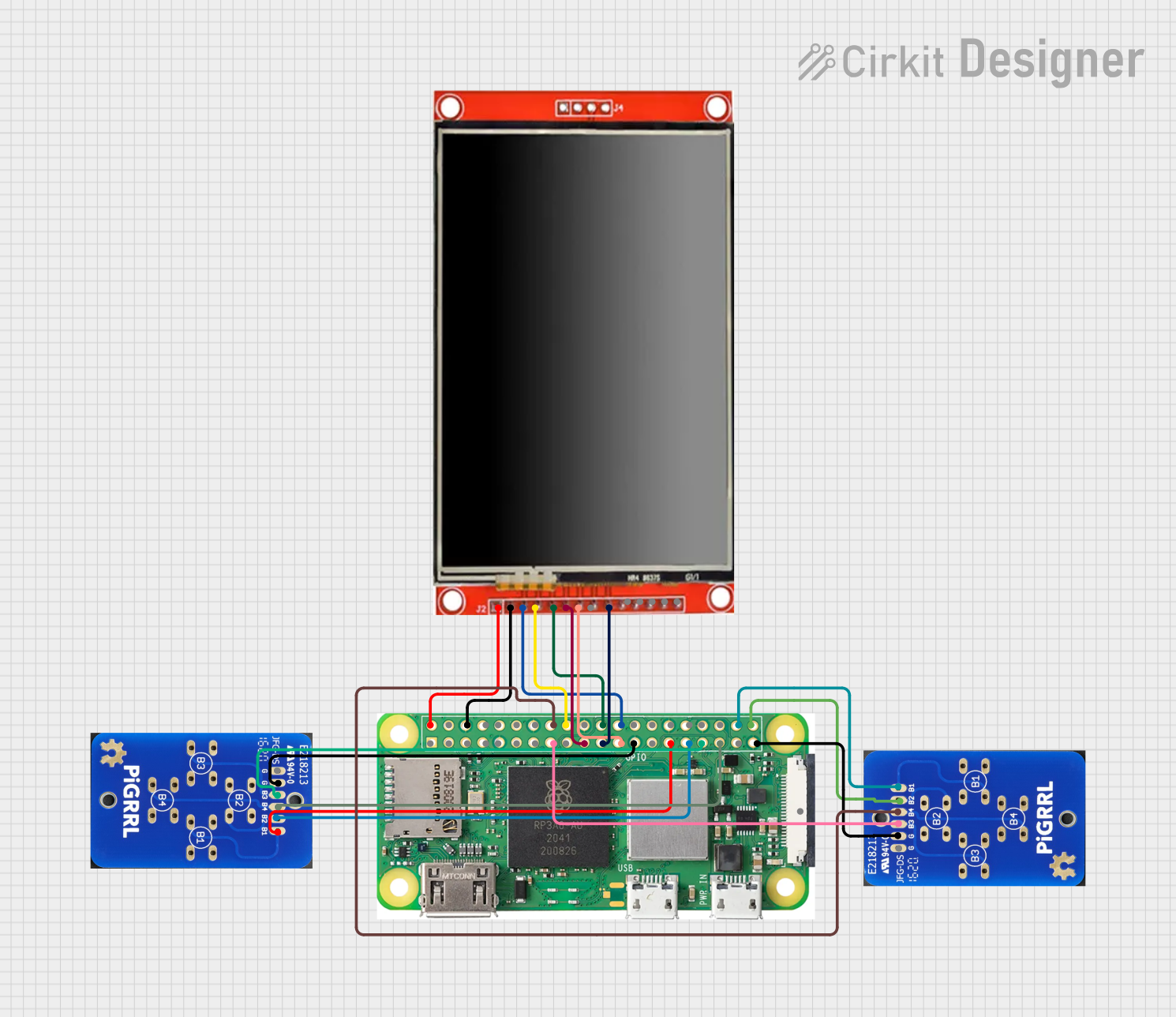
Explore Projects Built with Raspberry Pi Zero 2 W
Common Applications and Use Cases
- IoT devices and smart home automation
- Portable media streaming devices
- Lightweight web servers
- Robotics and embedded systems
- Educational tools for learning programming and electronics
- Retro gaming consoles
Technical Specifications
The Raspberry Pi Zero 2 W is equipped with a quad-core processor and wireless connectivity, making it a versatile and efficient computing platform.
Key Technical Details
| Specification | Details |
|---|---|
| Processor | Broadcom BCM2710A1, quad-core Cortex-A53 @ 1 GHz |
| RAM | 512 MB LPDDR2 |
| Wireless Connectivity | 802.11 b/g/n Wi-Fi, Bluetooth 4.2, BLE |
| GPIO | 40-pin GPIO header (unpopulated) |
| Video Output | Mini HDMI port, supports up to 1080p |
| USB | 1x Micro USB for data, 1x Micro USB for power |
| Storage | MicroSD card slot |
| Power Supply | 5V/2.5A via Micro USB |
| Dimensions | 65mm x 30mm x 5mm |
| Weight | Approximately 9g |
Pin Configuration and Descriptions
The Raspberry Pi Zero 2 W features a 40-pin GPIO header, which is unpopulated by default. Below is the pinout for the GPIO header:
| Pin Number | Pin Name | Functionality |
|---|---|---|
| 1 | 3.3V | Power (3.3V) |
| 2 | 5V | Power (5V) |
| 3 | GPIO2 (SDA1) | I2C Data |
| 4 | 5V | Power (5V) |
| 5 | GPIO3 (SCL1) | I2C Clock |
| 6 | GND | Ground |
| 7 | GPIO4 | General Purpose I/O |
| 8 | GPIO14 (TXD) | UART Transmit |
| 9 | GND | Ground |
| 10 | GPIO15 (RXD) | UART Receive |
| ... | ... | ... (Refer to official documentation for full pinout) |
Usage Instructions
How to Use the Raspberry Pi Zero 2 W in a Circuit
- Powering the Board: Use a 5V/2.5A power supply connected to the Micro USB power port.
- Connecting Peripherals: Attach a mini HDMI cable for video output, a USB OTG adapter for peripherals like a keyboard or mouse, and a microSD card with the Raspberry Pi OS installed.
- GPIO Usage: Solder the GPIO header if required, and connect sensors, actuators, or other components to the appropriate pins.
- Wireless Setup: Configure Wi-Fi and Bluetooth through the Raspberry Pi OS settings or via the command line.
Important Considerations and Best Practices
- Use a high-quality microSD card (Class 10 or higher) for optimal performance.
- Ensure proper heat dissipation if running CPU-intensive tasks for extended periods.
- Avoid powering the board through GPIO pins unless you are experienced with power management.
- Use level shifters when interfacing with 5V logic devices, as the GPIO operates at 3.3V.
Example: Connecting to an Arduino UNO
The Raspberry Pi Zero 2 W can communicate with an Arduino UNO via UART. Below is an example Python script for sending data from the Raspberry Pi to the Arduino:
import serial
import time
Initialize serial communication with the Arduino
Replace '/dev/ttyAMA0' with the correct port for your setup
arduino = serial.Serial('/dev/ttyAMA0', 9600, timeout=1) time.sleep(2) # Wait for the connection to initialize
try: while True: # Send a message to the Arduino arduino.write(b'Hello, Arduino!\n') print("Message sent to Arduino") time.sleep(1) # Wait before sending the next message except KeyboardInterrupt: print("Exiting program") finally: arduino.close() # Close the serial connection
**Note**: Ensure that the UART pins (GPIO14 and GPIO15) are connected to the Arduino's RX and TX pins, respectively, and that the baud rate matches on both devices.
Troubleshooting and FAQs
Common Issues Users Might Face
No Display Output:
- Ensure the mini HDMI cable is securely connected.
- Verify that the microSD card has a valid Raspberry Pi OS image.
- Check the power supply for sufficient voltage and current.
Wi-Fi Not Connecting:
- Double-check the Wi-Fi credentials in the Raspberry Pi OS settings.
- Ensure the Wi-Fi network is within range and not restricted by MAC filtering.
GPIO Not Responding:
- Verify the GPIO pins are correctly configured in your code.
- Check for loose connections or soldering issues on the GPIO header.
Overheating:
- Use a heatsink or fan if the board is running CPU-intensive tasks.
- Ensure proper ventilation around the board.
Solutions and Tips for Troubleshooting
- Use the
dmesgcommand to check for system errors or hardware issues. - Test the board with a different power supply and microSD card to rule out hardware faults.
- Refer to the official Raspberry Pi documentation for advanced debugging techniques.
By following this documentation, users can effectively utilize the Raspberry Pi Zero 2 W for a variety of projects and applications.