How to Use Adafruit WINC1500 Shield: Examples, Pinouts, and Specs
Introduction
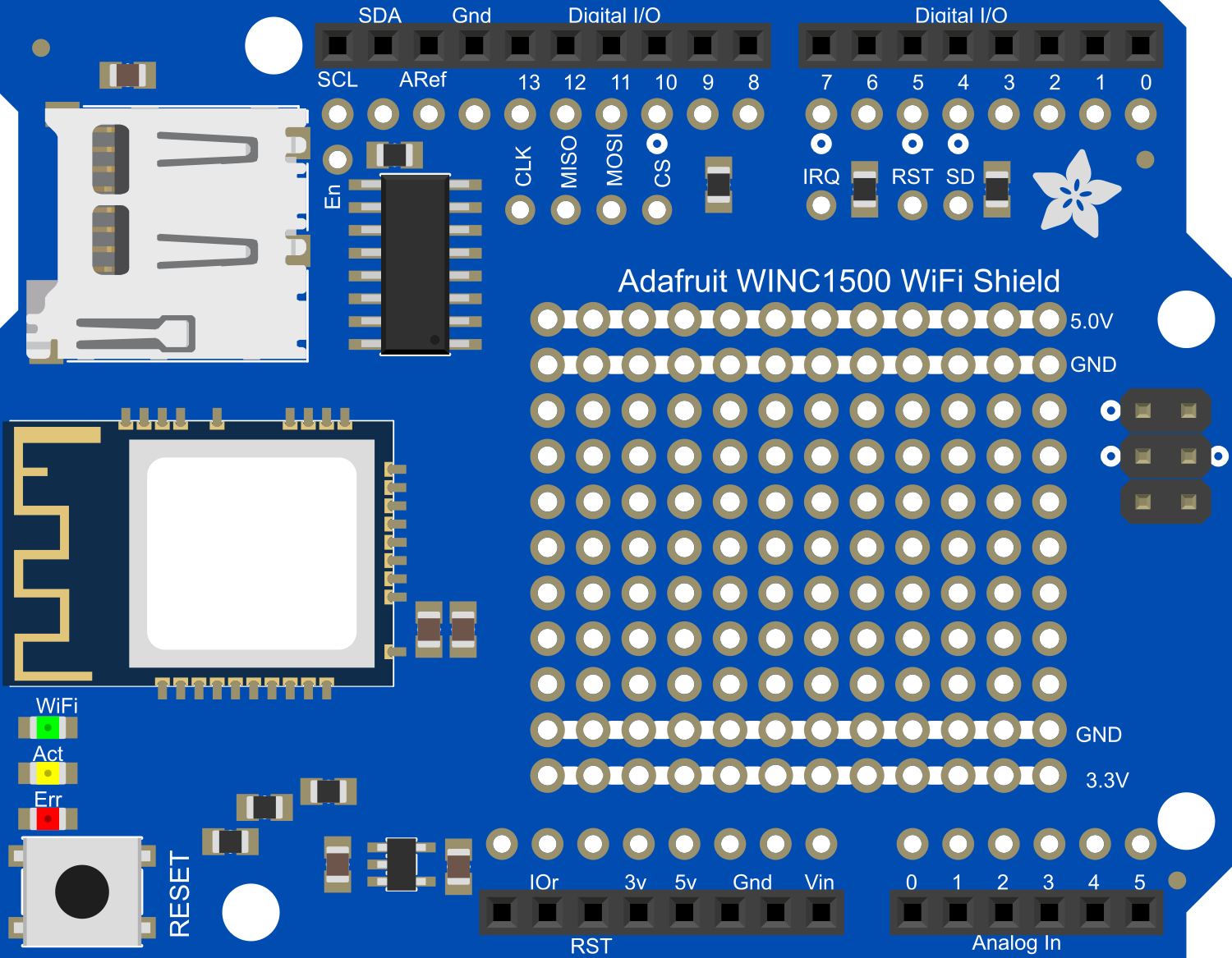
The Adafruit WINC1500 WiFi Shield is a powerful wireless networking module that enables Arduino and compatible microcontroller boards to connect to the internet. It is based on the ATWINC1500-MR210PB IEEE 802.11 b/g/n WiFi network controller. This shield supports both 2.4GHz and 5GHz WiFi networks, providing versatility for various wireless applications. Common use cases include home automation, IoT devices, data logging, and remote sensor monitoring.
Explore Projects Built with Adafruit WINC1500 Shield
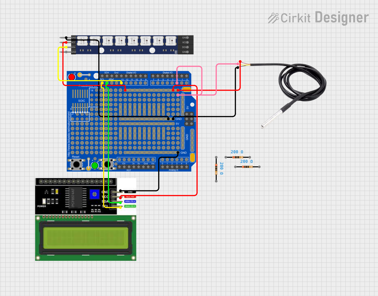
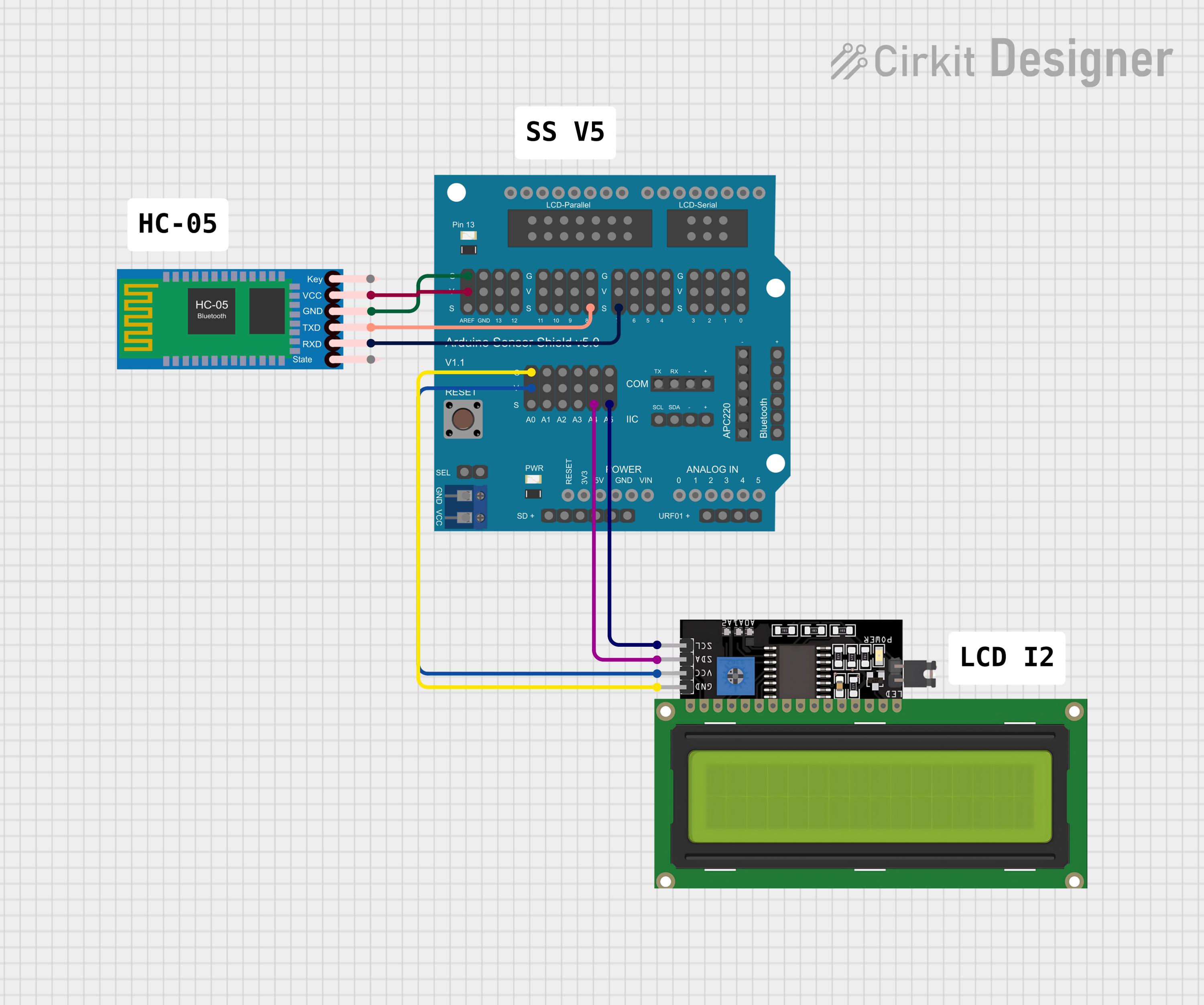
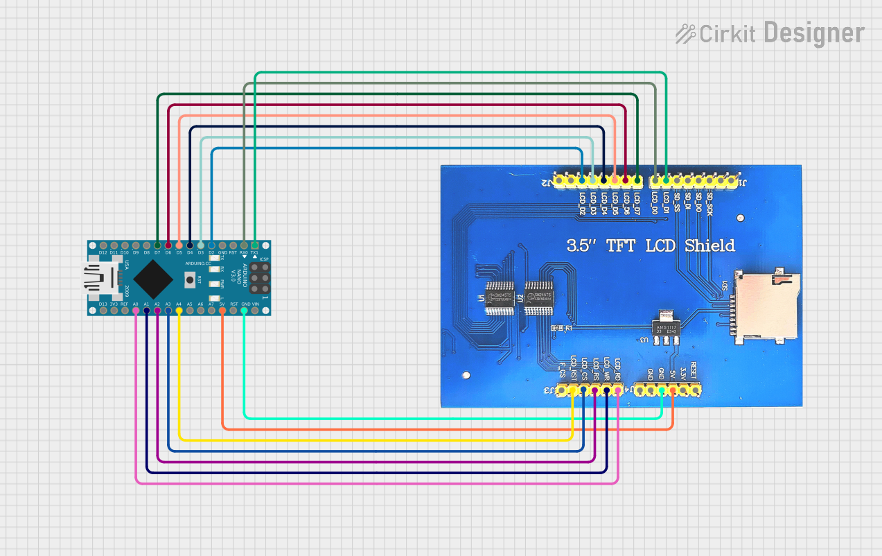
Explore Projects Built with Adafruit WINC1500 Shield
Technical Specifications
Key Technical Details
- WiFi Standards: IEEE 802.11 b/g/n
- Frequency Bands: 2.4GHz & 5GHz
- Security Protocols: WEP, WPA/WPA2 PSK
- Data Rates: Up to 72.2 Mbps with 20 MHz bandwidth
- Antenna: Integrated PCB antenna
- Interface: SPI
- Operating Voltage: 3.3V (5V tolerant pins)
- Current Consumption: ~250mA (max)
Pin Configuration and Descriptions
| Pin Number | Function | Description |
|---|---|---|
| D10 | CS | Chip Select for SPI interface |
| D11 | MOSI | Master Out Slave In for SPI interface |
| D12 | MISO | Master In Slave Out for SPI interface |
| D13 | SCK | Serial Clock for SPI interface |
| D7 | IRQ | Interrupt request pin |
| D5 | RST | Reset pin for the WINC1500 module |
| IOREF | Voltage Reference | Used to adapt the shield to the voltage provided by the board |
Usage Instructions
Connecting the Shield to an Arduino
- Align the WINC1500 shield pins with the headers on your Arduino board.
- Gently press down to ensure a firm connection without bending the pins.
- Verify that the shield is seated properly and there are no loose connections.
Software Setup
- Install the Adafruit WINC1500 library through the Arduino Library Manager.
- Include the library in your sketch by adding
#include <WiFi101.h>at the beginning of your code. - Initialize the WiFi module in your
setup()function usingWiFi.begin(ssid, pass).
Example Code
#include <SPI.h>
#include <WiFi101.h>

char ssid[] = "yourNetwork";     // your network SSID (name)
char pass[] = "secretPassword";  // your network password

void setup() {
  // Initialize serial communication for debugging
  Serial.begin(9600);
  while (!Serial) {
    ; // Wait for serial port to connect.
  }

  // Check for the presence of the shield
  if (WiFi.status() == WL_NO_SHIELD) {
    Serial.println("WiFi shield not present");
    // Don't continue if the shield is not present
    while (true);
  }

  // Attempt to connect to WiFi network
  while (WiFi.begin(ssid, pass) != WL_CONNECTED) {
    Serial.print("Attempting to connect to SSID: ");
    Serial.println(ssid);
    // Wait 10 seconds before retrying
    delay(10000);
  }

  Serial.println("Connected to wifi");
  printWiFiStatus();
}

void loop() {
  // Nothing here for now.
}

void printWiFiStatus() {
  // Print the SSID of the network you're attached to
  Serial.print("SSID: ");
  Serial.println(WiFi.SSID());

  // Print your board's IP address
  IPAddress ip = WiFi.localIP();
  Serial.print("IP Address: ");
  Serial.println(ip);

  // Print the received signal strength
  long rssi = WiFi.RSSI();
  Serial.print("Signal strength (RSSI):");
  Serial.print(rssi);
  Serial.println(" dBm");
}
Important Considerations and Best Practices
- Ensure that the power supply to the Arduino can handle the additional current drawn by the WiFi shield.
- Use a level shifter if you are interfacing with a 5V microcontroller to prevent damage to the WINC1500 module.
- Place the shield in a location with minimal interference to ensure a stable connection.
- Always disconnect the shield from power before making or altering connections.
Troubleshooting and FAQs
Common Issues
- Shield not detected: Ensure the shield is properly seated on the Arduino. Check for any bent pins or loose connections.
- Unable to connect to WiFi: Verify that the SSID and password are correct. Ensure that the WiFi network is within range and operating.
- Intermittent connectivity: Check for sources of electromagnetic interference near the shield or WiFi router.
Solutions and Tips
- Reset the WINC1500 module: Use the RST pin to reset the module if it becomes unresponsive.
- Update firmware: Ensure the WINC1500 firmware is up to date using the firmware update tool provided by Adafruit.
- Signal strength: Use the
WiFi.RSSI()function to check the signal strength and move the device closer to the router if necessary.
FAQs
Can the shield connect to 5GHz networks? Yes, the WINC1500 supports both 2.4GHz and 5GHz networks.
Is the shield compatible with all Arduino boards? The shield is designed for boards that are compatible with the Arduino Uno form factor. For other boards, check the pin compatibility and voltage levels.
How do I update the shield's firmware? Adafruit provides a guide and software tool for updating the WINC1500 firmware. Follow the instructions provided in their official documentation.
Remember to check the Adafruit forums and the product guide for additional support and updates.