How to Use ESP32 - CAM: Examples, Pinouts, and Specs
Introduction
The ESP32-CAM is a low-cost development board that combines the powerful ESP32 microcontroller with integrated Wi-Fi and Bluetooth capabilities, along with a camera module. This compact and versatile board is ideal for IoT projects that require image capture, video streaming, or remote monitoring. Its small form factor and rich feature set make it a popular choice for applications such as home automation, security systems, and AI-based image recognition.
Explore Projects Built with ESP32 - CAM


Explore Projects Built with ESP32 - CAM
Common Applications and Use Cases
- Wireless video streaming and surveillance systems
- Smart home devices with image or video capture
- AI-powered image recognition and processing
- Remote monitoring for IoT projects
- DIY robotics with vision capabilities
Technical Specifications
The ESP32-CAM is equipped with a range of features that make it suitable for various applications. Below are its key technical specifications:
Key Technical Details
- Microcontroller: ESP32-D0WDQ6
- Wireless Connectivity: Wi-Fi 802.11 b/g/n and Bluetooth 4.2 (BLE)
- Camera Module: OV2640 (2MP resolution)
- Flash Memory: 4MB (PSRAM: 8MB)
- Operating Voltage: 3.3V
- Input Voltage Range: 5V (via external power supply)
- GPIO Pins: 9 available for user applications
- Interfaces: UART, SPI, I2C, PWM
- Image Output Formats: JPEG, BMP, GRAYSCALE
- Dimensions: 27mm x 40.5mm
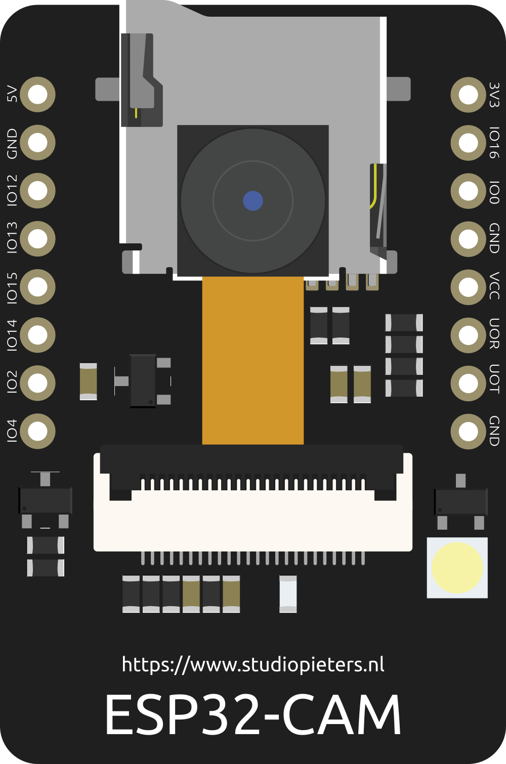
Pin Configuration and Descriptions
The ESP32-CAM has a total of 16 pins. Below is the pinout and description:
| Pin Name | Description |
|---|---|
| GND | Ground pin |
| 3.3V | 3.3V power output |
| 5V | 5V power input |
| GPIO0 | Used for boot mode selection (connect to GND for programming) |
| GPIO1 (U0TXD) | UART0 Transmit (TX) |
| GPIO3 (U0RXD) | UART0 Receive (RX) |
| GPIO4 | General-purpose I/O pin |
| GPIO12 | General-purpose I/O pin |
| GPIO13 | General-purpose I/O pin |
| GPIO14 | General-purpose I/O pin |
| GPIO15 | General-purpose I/O pin |
| GPIO16 | General-purpose I/O pin |
| GPIO33 | General-purpose I/O pin |
| GPIO34 | General-purpose I/O pin (input only) |
| RESET | Reset pin |
| SD Card Pins | SD card interface (CLK, CMD, DATA0, DATA1, DATA2, DATA3) |
Note: GPIO0 must be connected to GND during programming. Disconnect it after flashing the firmware.
Usage Instructions
The ESP32-CAM can be used in a variety of projects. Below are the steps to get started and important considerations.
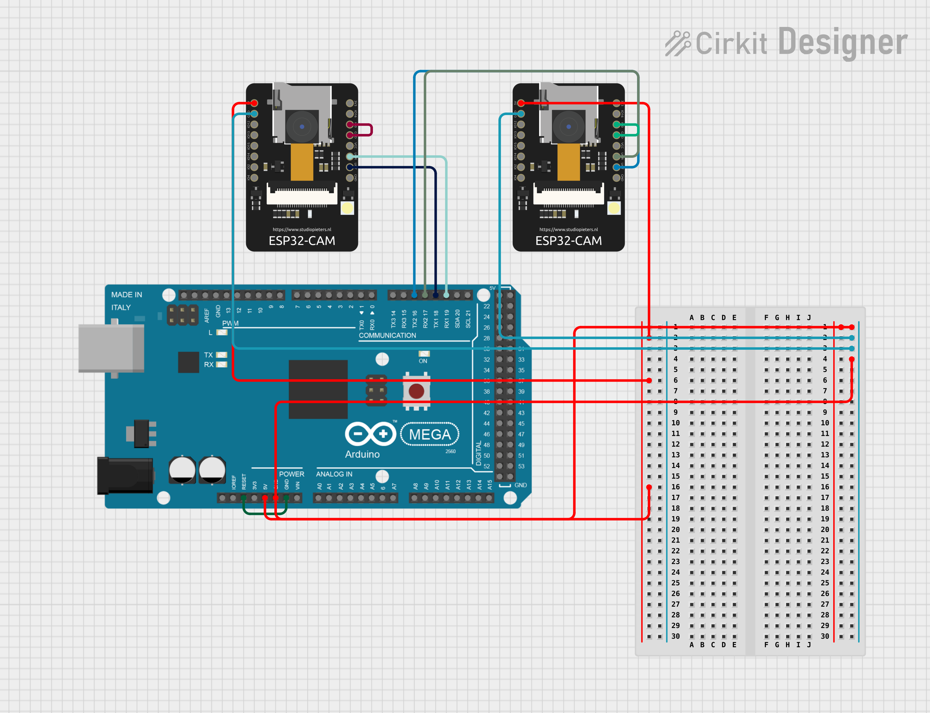
How to Use the ESP32-CAM in a Circuit
Powering the Board:
- Use a 5V power supply connected to the 5V and GND pins.
- Alternatively, you can power the board via a USB-to-TTL adapter.
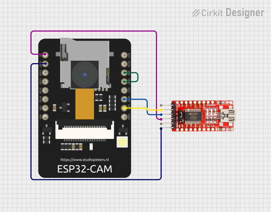
Programming the Board:
- Connect the ESP32-CAM to a USB-to-TTL adapter as follows:
- TX (adapter) → U0RXD (ESP32-CAM)
- RX (adapter) → U0TXD (ESP32-CAM)
- GND (adapter) → GND (ESP32-CAM)
- 5V (adapter) → 5V (ESP32-CAM)
- Connect GPIO0 to GND to enable programming mode.
- Use the Arduino IDE or ESP-IDF to upload your code.
- Connect the ESP32-CAM to a USB-to-TTL adapter as follows:
Connecting the Camera:
- Ensure the OV2640 camera module is securely connected to the camera port on the ESP32-CAM.
Using the SD Card:
- Insert a microSD card into the slot for image or video storage.
- Ensure the card is formatted as FAT32.
Important Considerations and Best Practices
- Heat Management: The ESP32-CAM can get hot during operation. Use a heatsink if necessary.
- Power Supply: Ensure a stable 5V power source to avoid unexpected resets or instability.
- Antenna: For better Wi-Fi performance, use an external antenna if the onboard antenna is insufficient.
- GPIO Limitations: Some GPIO pins are used internally (e.g., for the camera or SD card) and may not be available for general use.
Example Code for Arduino IDE
Below is an example of how to use the ESP32-CAM for video streaming:
#include <WiFi.h>
#include <esp_camera.h>

// Replace with your network credentials
const char* ssid = "Your_SSID";
const char* password = "Your_PASSWORD";

void startCameraServer();

void setup() {
  Serial.begin(115200);

  // Connect to Wi-Fi
  WiFi.begin(ssid, password);
  while (WiFi.status() != WL_CONNECTED) {
    delay(500);
    Serial.print(".");
  }
  Serial.println("");
  Serial.println("WiFi connected");
  Serial.println("IP address: ");
  Serial.println(WiFi.localIP());

  // Initialize the camera
  camera_config_t config;
  config.ledc_channel = LEDC_CHANNEL_0;
  config.ledc_timer = LEDC_TIMER_0;
  config.pin_d0 = Y2_GPIO_NUM;
  config.pin_d1 = Y3_GPIO_NUM;
  config.pin_d2 = Y4_GPIO_NUM;
  config.pin_d3 = Y5_GPIO_NUM;
  config.pin_d4 = Y6_GPIO_NUM;
  config.pin_d5 = Y7_GPIO_NUM;
  config.pin_d6 = Y8_GPIO_NUM;
  config.pin_d7 = Y9_GPIO_NUM;
  config.pin_xclk = XCLK_GPIO_NUM;
  config.pin_pclk = PCLK_GPIO_NUM;
  config.pin_vsync = VSYNC_GPIO_NUM;
  config.pin_href = HREF_GPIO_NUM;
  config.pin_sscb_sda = SIOD_GPIO_NUM;
  config.pin_sscb_scl = SIOC_GPIO_NUM;
  config.pin_pwdn = PWDN_GPIO_NUM;
  config.pin_reset = RESET_GPIO_NUM;
  config.xclk_freq_hz = 20000000;
  config.pixel_format = PIXFORMAT_JPEG;

  // Initialize the camera
  if (esp_camera_init(&config) != ESP_OK) {
    Serial.println("Camera init failed");
    return;
  }

  // Start the camera server
  startCameraServer();
}

void loop() {
  // Nothing to do here
}
Note: Replace
Your_SSIDandYour_PASSWORDwith your Wi-Fi credentials.
Troubleshooting and FAQs
Common Issues and Solutions
Camera Initialization Failed:
- Ensure the camera module is properly connected.
- Check the power supply for stability.
Wi-Fi Connection Issues:
- Verify the SSID and password.
- Ensure the router is within range.
Board Not Detected During Programming:
- Ensure GPIO0 is connected to GND.
- Check the USB-to-TTL adapter connections.
Overheating:
- Use a heatsink or improve ventilation around the board.
FAQs
Can I use the ESP32-CAM without an SD card?
Yes, the SD card is optional and only required for storing images or videos locally.What is the maximum resolution of the camera?
The OV2640 camera supports up to 1600x1200 (UXGA) resolution.Can I use the ESP32-CAM with an external antenna?
Yes, you can switch to an external antenna by modifying the onboard antenna jumper.
By following this documentation, you can effectively use the ESP32-CAM for your IoT and vision-based projects.