How to Use PZEM: Examples, Pinouts, and Specs

Introduction
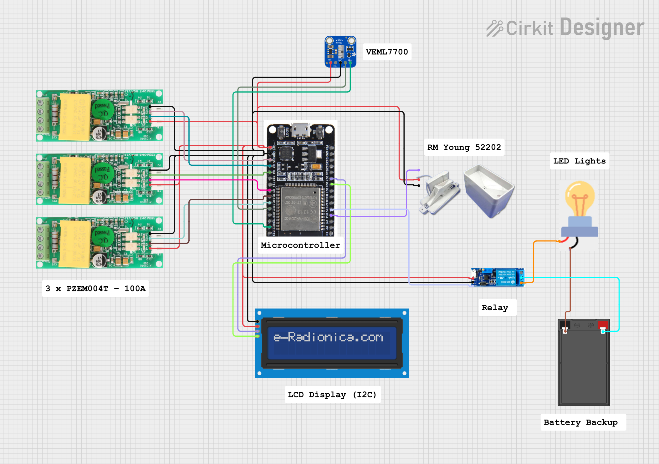
The PZEM-017 is a power monitoring module designed for measuring key electrical parameters in AC circuits. It can measure voltage, current, power, energy, and frequency, providing real-time data for energy management and monitoring applications. The module communicates via UART, making it easy to integrate with microcontrollers and other systems. Its compact design and reliable performance make it ideal for use in smart homes, industrial automation, and energy monitoring systems.
Explore Projects Built with PZEM


Explore Projects Built with PZEM
Common Applications
- Smart home energy monitoring
- Industrial power management
- Renewable energy systems
- Load analysis and optimization
- Educational and research projects
Technical Specifications
The PZEM-017 module is designed to operate in AC circuits and provides accurate measurements of electrical parameters. Below are the key technical details:
| Parameter | Specification |
|---|---|
| Voltage Range | 80V - 260V AC |
| Current Range | 0A - 100A (with external current transformer) |
| Power Range | 0W - 22kW |
| Energy Range | 0kWh - 9999kWh |
| Frequency Range | 45Hz - 65Hz |
| Communication Interface | UART (9600 baud rate) |
| Power Supply | 5V DC |
| Accuracy | ±0.5% |
| Operating Temperature | -10°C to 60°C |
| Dimensions | 70mm x 40mm x 20mm |
Pin Configuration
The PZEM-017 module has a simple pinout for easy integration. Below is the pin configuration:
| Pin Name | Description |
|---|---|
| VCC | 5V DC power supply input |
| GND | Ground |
| TX | UART Transmit (connect to RX of microcontroller) |
| RX | UART Receive (connect to TX of microcontroller) |
| AC-IN | AC voltage input (connect to live and neutral wires) |
| CT-IN | Current transformer input (connect to external CT sensor) |
Usage Instructions
Connecting the PZEM-017
- Power Supply: Connect the VCC pin to a 5V DC power source and the GND pin to ground.
- AC Input: Connect the AC-IN terminals to the live and neutral wires of the AC circuit you want to monitor.
- Current Transformer: Attach the external current transformer (CT) to the CT-IN terminals. Ensure the CT is clamped around the live wire of the AC circuit.
- UART Communication: Connect the TX pin of the PZEM-017 to the RX pin of your microcontroller, and the RX pin of the PZEM-017 to the TX pin of your microcontroller.
Important Considerations
- Ensure proper insulation and safety precautions when working with AC circuits.
- Use a compatible current transformer (e.g., 100A/50mA) for accurate current measurement.
- Avoid exceeding the specified voltage and current ranges to prevent damage to the module.
- Use a stable 5V DC power supply to ensure reliable operation.
Example Code for Arduino UNO
Below is an example Arduino sketch to interface the PZEM-017 with an Arduino UNO using UART communication:
#include <SoftwareSerial.h>

// Define RX and TX pins for SoftwareSerial
SoftwareSerial pzemSerial(10, 11); // RX = Pin 10, TX = Pin 11

// Command to read voltage (example command for PZEM-017)
byte readVoltageCmd[] = {0xB0, 0xC0, 0xA8, 0x01, 0x01, 0x00, 0x1A};

// Function to send command and read response
void sendCommand(byte* cmd, int cmdLength) {
  pzemSerial.write(cmd, cmdLength); // Send command to PZEM
  delay(100); // Wait for response
  while (pzemSerial.available()) {
    byte response = pzemSerial.read(); // Read response byte by byte
    Serial.print(response, HEX); // Print response in HEX format
    Serial.print(" ");
  }
  Serial.println();
}

void setup() {
  Serial.begin(9600); // Initialize Serial Monitor
  pzemSerial.begin(9600); // Initialize SoftwareSerial for PZEM
  Serial.println("PZEM-017 Power Monitoring Module");
}

void loop() {
  Serial.print("Reading Voltage: ");
  sendCommand(readVoltageCmd, sizeof(readVoltageCmd)); // Send voltage read command
  delay(2000); // Wait 2 seconds before next reading
}
Notes:
- Replace
readVoltageCmdwith appropriate commands to read other parameters (e.g., current, power). - Ensure the RX and TX pins are correctly connected between the Arduino and PZEM-017.
Troubleshooting and FAQs
Common Issues
No Data Received from the Module
- Solution: Check the UART connections (TX and RX). Ensure the TX of the PZEM-017 is connected to the RX of the microcontroller and vice versa.
- Solution: Verify the baud rate is set to 9600 in your code.
Incorrect Voltage or Current Readings
- Solution: Ensure the AC-IN terminals are properly connected to the live and neutral wires.
- Solution: Verify the current transformer is securely clamped around the live wire and is compatible with the module.
Module Not Powering On
- Solution: Check the 5V DC power supply and ensure proper connections to the VCC and GND pins.
FAQs
Can the PZEM-017 measure DC circuits?
- No, the PZEM-017 is designed specifically for AC circuits.
What is the maximum current the module can measure?
- The module can measure up to 100A when used with a compatible current transformer.
Can I use the PZEM-017 with a Raspberry Pi?
- Yes, the PZEM-017 can be used with a Raspberry Pi via UART communication. Use appropriate libraries or write custom code to interface with the module.
How do I reset the energy counter?
- The energy counter can be reset by sending a specific command via UART. Refer to the manufacturer's documentation for the reset command.
By following this documentation, you can effectively integrate the PZEM-017 into your projects for accurate power monitoring and energy management.