How to Use AS7265X: Examples, Pinouts, and Specs
Introduction
The AS7265X is a multi-spectral sensor capable of detecting light across six different wavelengths, making it ideal for applications requiring precise spectral analysis. This sensor is widely used in color sensing, environmental monitoring, material analysis, and other fields where high-resolution spectral data is essential. Its I2C interface ensures seamless integration with microcontrollers, enabling developers to incorporate advanced spectral sensing into their projects with ease.
Explore Projects Built with AS7265X


Explore Projects Built with AS7265X
Common Applications:
- Color sensing for industrial and consumer devices
- Environmental monitoring (e.g., detecting pollutants or light conditions)
- Material analysis in scientific and industrial settings
- Precision agriculture for analyzing soil and plant health
- Medical diagnostics and laboratory instrumentation
Technical Specifications
The AS7265X sensor is designed to provide accurate and reliable spectral data. Below are its key technical details:
Key Specifications:
| Parameter | Value |
|---|---|
| Operating Voltage | 3.3V (typical) |
| Communication Interface | I2C |
| Spectral Channels | 6 (multi-spectral detection) |
| Wavelength Range | 410 nm to 940 nm |
| Operating Temperature | -40°C to +85°C |
| Power Consumption | Low power (dependent on usage mode) |
| Package Type | LGA |
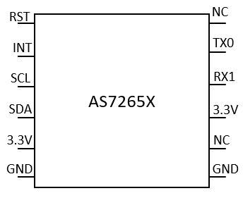
Pin Configuration:
The AS7265X sensor has the following pin configuration:
| Pin Number | Pin Name | Description |
|---|---|---|
| 1 | VDD | Power supply (3.3V) |
| 2 | GND | Ground |
| 3 | SDA | I2C data line |
| 4 | SCL | I2C clock line |
| 5 | INT | Interrupt output (optional) |
| 6 | RST | Reset pin (active low) |
Usage Instructions
The AS7265X sensor is straightforward to use in a circuit, thanks to its I2C interface. Below are the steps and best practices for integrating the sensor into your project:
Connecting the AS7265X to a Microcontroller:
- Power Supply: Connect the
VDDpin to a 3.3V power source and theGNDpin to ground. - I2C Communication: Connect the
SDAandSCLpins to the corresponding I2C pins on your microcontroller. - Optional Connections:
- Use the
INTpin if you want to handle interrupts. - Connect the
RSTpin to a GPIO pin on your microcontroller for manual resets, or tie it toVDDif not used.
- Use the
Example Code for Arduino UNO:
Below is an example of how to interface the AS7265X with an Arduino UNO using the I2C protocol. Note that the Arduino UNO operates at 5V logic, so a level shifter is required to safely interface with the 3.3V AS7265X.
#include <Wire.h>

// AS7265X I2C address
#define AS7265X_ADDR 0x49

void setup() {
  Wire.begin(); // Initialize I2C communication
  Serial.begin(9600); // Initialize serial communication for debugging

  // Check if the sensor is connected
  Wire.beginTransmission(AS7265X_ADDR);
  if (Wire.endTransmission() == 0) {
    Serial.println("AS7265X detected!");
  } else {
    Serial.println("AS7265X not detected. Check connections.");
    while (1); // Halt execution if sensor is not found
  }

  // Additional initialization code for the sensor can be added here
}

void loop() {
  // Example: Read spectral data (replace with actual register addresses)
  Wire.beginTransmission(AS7265X_ADDR);
  Wire.write(0x00); // Replace with the register address for spectral data
  Wire.endTransmission();

  Wire.requestFrom(AS7265X_ADDR, 6); // Request 6 bytes of spectral data
  if (Wire.available() == 6) {
    Serial.print("Spectral Data: ");
    for (int i = 0; i < 6; i++) {
      Serial.print(Wire.read(), HEX);
      Serial.print(" ");
    }
    Serial.println();
  }

  delay(1000); // Wait 1 second before the next reading
}
Best Practices:
- Use pull-up resistors (typically 4.7kΩ) on the
SDAandSCLlines if your microcontroller does not have internal pull-ups. - Ensure proper level shifting if your microcontroller operates at 5V logic.
- Avoid exposing the sensor to extreme environmental conditions beyond its operating range.
Troubleshooting and FAQs
Common Issues:
Sensor Not Detected on I2C Bus:
- Cause: Incorrect wiring or missing pull-up resistors.
- Solution: Double-check the connections and ensure pull-up resistors are present on the
SDAandSCLlines.
Incorrect or No Spectral Data:
- Cause: Improper initialization or incorrect register access.
- Solution: Verify that the sensor is properly initialized and that the correct register addresses are being used.
Intermittent Communication Failures:
- Cause: Noise on the I2C lines or insufficient power supply.
- Solution: Use shorter wires for I2C connections and ensure a stable 3.3V power supply.
FAQs:
Q: Can the AS7265X operate at 5V?
A: No, the AS7265X operates at 3.3V. Use a level shifter if interfacing with a 5V microcontroller.
Q: How do I calibrate the sensor?
A: Calibration procedures depend on the specific application. Refer to the manufacturer's datasheet for detailed calibration instructions.
Q: Can I use multiple AS7265X sensors on the same I2C bus?
A: Yes, but you will need to configure each sensor with a unique I2C address if supported, or use an I2C multiplexer.
By following this documentation, you can effectively integrate the AS7265X into your projects and leverage its advanced spectral sensing capabilities.