How to Use ESP32-2432S028: Examples, Pinouts, and Specs
Introduction
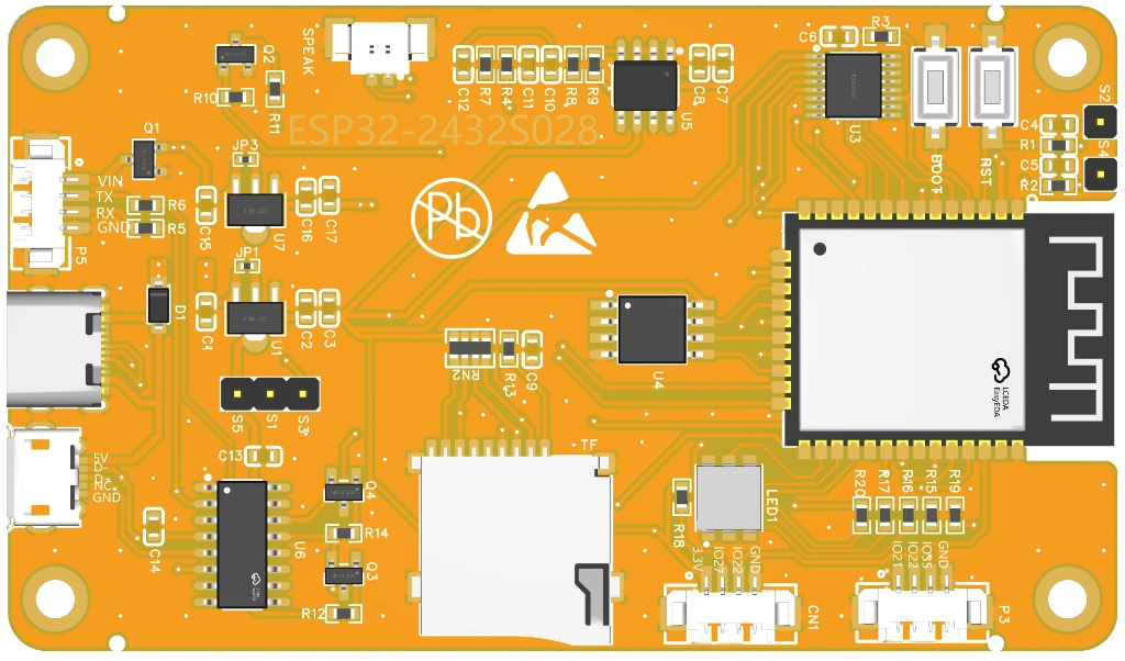
The ESP32-2432S028 is a versatile and powerful microcontroller module designed for IoT and embedded system applications. It features a dual-core processor, integrated Wi-Fi and Bluetooth capabilities, and a 2.8-inch TFT LCD display for user interaction. With its ample GPIO pins and support for various peripherals, the ESP32-2432S028 is ideal for projects requiring wireless communication, graphical interfaces, and real-time processing.
Explore Projects Built with ESP32-2432S028


Explore Projects Built with ESP32-2432S028
Common Applications and Use Cases
- IoT devices and smart home automation
- Industrial control systems
- Wearable technology
- Data logging and monitoring systems
- Wireless communication hubs
- Graphical user interface (GUI) development
Technical Specifications
The ESP32-2432S028 combines the power of the ESP32 microcontroller with a built-in 2.8-inch TFT LCD display. Below are the key technical details:
General Specifications
| Parameter | Value |
|---|---|
| Microcontroller | ESP32 (dual-core, 32-bit) |
| Clock Speed | Up to 240 MHz |
| Flash Memory | 4 MB |
| SRAM | 520 KB |
| Wireless Connectivity | Wi-Fi 802.11 b/g/n, Bluetooth |
| Display | 2.8-inch TFT LCD, 320x240 px |
| Operating Voltage | 3.3V |
| Input Voltage Range | 5V (via USB) or 3.3V (direct) |
| GPIO Pins | 28 |
| Communication Interfaces | UART, SPI, I2C, PWM, ADC, DAC |
| Dimensions | 85mm x 55mm x 12mm |
Pin Configuration and Descriptions
The ESP32-2432S028 has a total of 28 GPIO pins, which can be configured for various functions. Below is the pinout description:
| Pin Number | Pin Name | Functionality |
|---|---|---|
| 1 | GND | Ground |
| 2 | 3.3V | Power supply (3.3V output) |
| 3 | GPIO0 | General-purpose I/O, boot mode select |
| 4 | GPIO1 | UART TX |
| 5 | GPIO2 | General-purpose I/O |
| 6 | GPIO3 | UART RX |
| 7 | GPIO4 | PWM, ADC, or GPIO |
| 8 | GPIO5 | SPI SCK or GPIO |
| 9 | GPIO12 | ADC, GPIO |
| 10 | GPIO13 | ADC, GPIO |
| 11 | GPIO14 | SPI MISO or GPIO |
| 12 | GPIO15 | SPI MOSI or GPIO |
| 13 | GPIO16 | I2C SDA or GPIO |
| 14 | GPIO17 | I2C SCL or GPIO |
| ... | ... | ... (remaining pins follow similar) |
Note: Some GPIO pins have specific functions during boot. Refer to the ESP32 datasheet for details.
Usage Instructions
How to Use the ESP32-2432S028 in a Circuit
Powering the Module:
- Use a 5V USB power supply or provide 3.3V directly to the 3.3V pin.
- Ensure the power source can supply at least 500mA for stable operation.
Connecting Peripherals:
- Use the GPIO pins to connect sensors, actuators, or other peripherals.
- For communication, use UART, SPI, or I2C interfaces as required.
Programming the ESP32:
- Install the Arduino IDE or ESP-IDF (Espressif IoT Development Framework).
- Select "ESP32 Dev Module" as the board in the Arduino IDE.
- Connect the module to your computer via USB and upload your code.
Using the TFT Display:
- The built-in 2.8-inch TFT LCD can be controlled using libraries like
TFT_eSPI. - Configure the display pins in your code to match the module's pinout.
- The built-in 2.8-inch TFT LCD can be controlled using libraries like
Example Code for Arduino IDE
The following example demonstrates how to display text on the TFT screen and toggle an LED:
#include <TFT_eSPI.h> // Include the TFT library
#include <Wire.h>     // Include the I2C library

TFT_eSPI tft = TFT_eSPI(); // Create TFT object

#define LED_PIN 2 // Define the LED pin (GPIO2)

void setup() {
  pinMode(LED_PIN, OUTPUT); // Set LED pin as output
  tft.init();               // Initialize the TFT display
  tft.setRotation(1);       // Set display orientation
  tft.fillScreen(TFT_BLACK); // Clear the screen
  tft.setTextColor(TFT_WHITE, TFT_BLACK); // Set text color

  tft.setCursor(10, 10);    // Set cursor position
  tft.setTextSize(2);       // Set text size
  tft.println("Hello, ESP32!"); // Display text

  digitalWrite(LED_PIN, HIGH); // Turn on the LED
}

void loop() {
  digitalWrite(LED_PIN, !digitalRead(LED_PIN)); // Toggle LED state
  delay(500); // Wait for 500ms
}
Important Considerations and Best Practices
- Power Supply: Ensure a stable power supply to avoid unexpected resets or malfunctions.
- GPIO Usage: Avoid using GPIO0, GPIO2, and GPIO15 for general I/O as they have specific boot functions.
- Heat Management: The ESP32 may heat up during operation. Ensure proper ventilation.
- Firmware Updates: Keep the ESP32 firmware updated for optimal performance and security.
Troubleshooting and FAQs
Common Issues and Solutions
Module Not Detected by Computer:
- Ensure the USB cable is functional and supports data transfer.
- Install the correct USB-to-serial driver for the ESP32.
Program Upload Fails:
- Check the selected board and port in the Arduino IDE.
- Hold the BOOT button while uploading to force the module into programming mode.
Wi-Fi Connection Issues:
- Verify the SSID and password in your code.
- Ensure the router is within range and supports 2.4 GHz Wi-Fi.
TFT Display Not Working:
- Check the wiring and pin configuration in your code.
- Ensure the
TFT_eSPIlibrary is correctly installed and configured.
FAQs
Q: Can I power the ESP32-2432S028 with a battery?
A: Yes, you can use a 3.7V LiPo battery with a suitable voltage regulator to provide 3.3V.
Q: Is the module compatible with MicroPython?
A: Yes, the ESP32-2432S028 supports MicroPython. You can flash the MicroPython firmware to the module.
Q: How do I reset the module?
A: Press the RESET button on the module to restart it.
Q: Can I use the TFT display and Wi-Fi simultaneously?
A: Yes, the ESP32's dual-core processor allows multitasking, enabling simultaneous use of the display and Wi-Fi.
By following this documentation, you can effectively utilize the ESP32-2432S028 for your projects.