
How to Use Teensy 2.0: Examples, Pinouts, and Specs

 Design with Teensy 2.0 in Cirkit Designer
Introduction
The Teensy 2.0 is a compact and powerful microcontroller board based on the ATmega32U4 microcontroller. It is designed for projects requiring USB connectivity, real-time processing, and a small form factor. With its built-in USB functionality, the Teensy 2.0 can emulate various USB devices, such as keyboards, mice, and game controllers, making it a versatile choice for hobbyists and professionals alike.
Explore Projects Built with Teensy 2.0
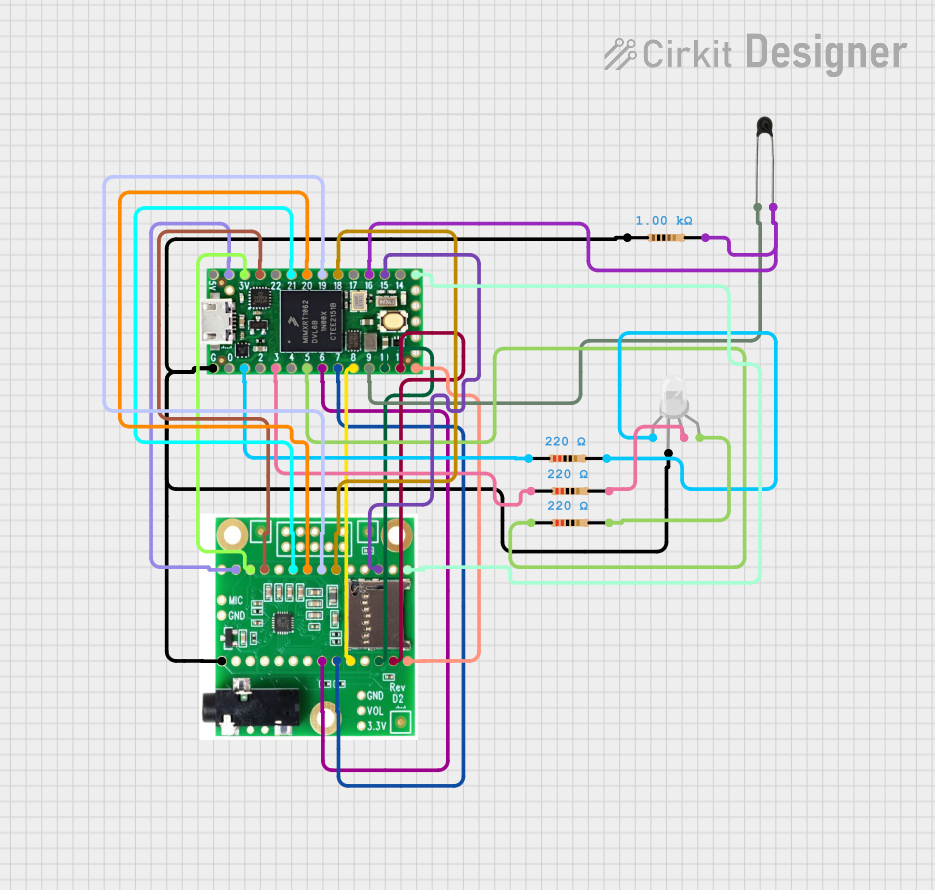 Open Project in Cirkit Designer
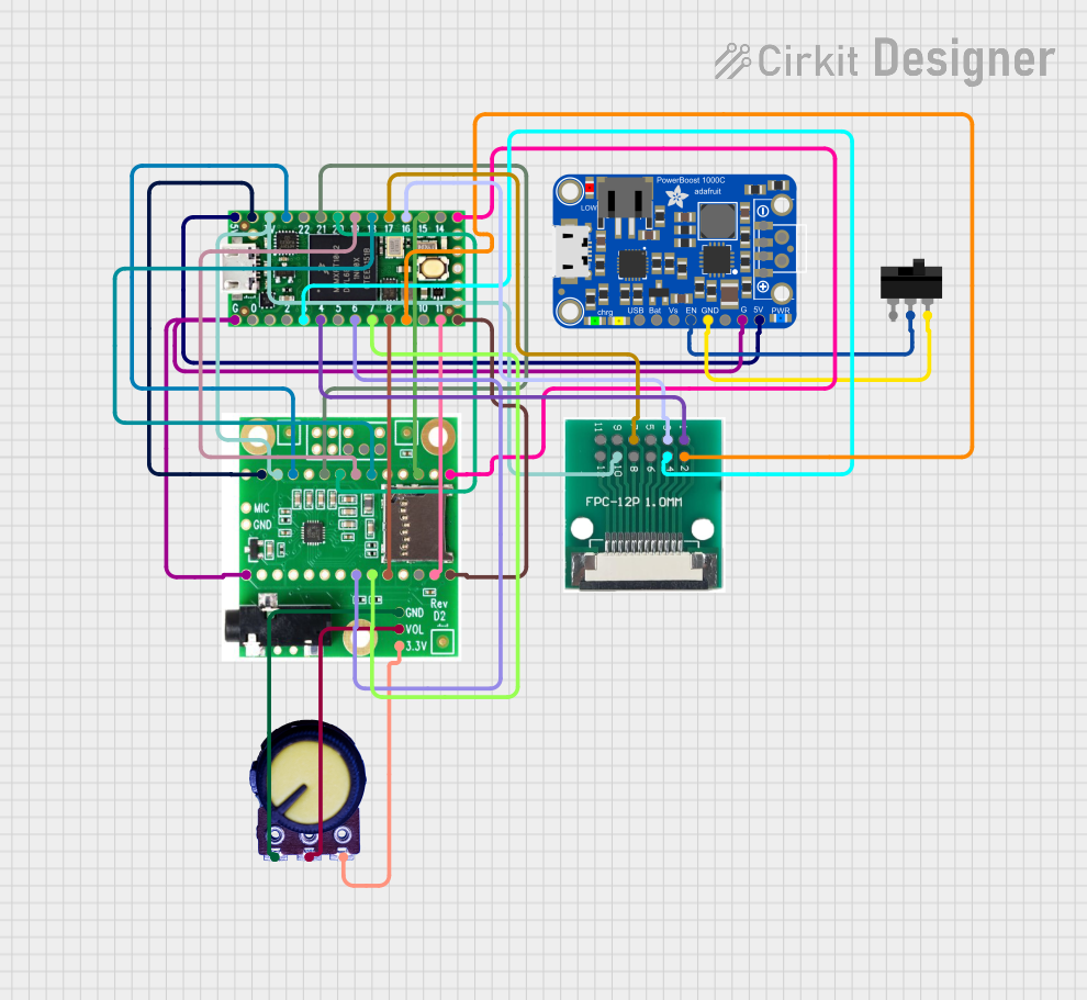 Open Project in Cirkit Designer
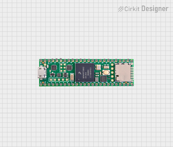 Open Project in Cirkit Designer
 Open Project in Cirkit Designer
Explore Projects Built with Teensy 2.0
Open Project in Cirkit DesignerOpen Project in Cirkit DesignerOpen Project in Cirkit DesignerOpen Project in Cirkit DesignerCommon Applications and Use Cases
- USB device emulation (e.g., keyboards, mice, MIDI controllers)
- Robotics and automation
- Real-time data acquisition and processing
- DIY electronics projects
- Prototyping and development of USB-based devices
Technical Specifications
Key Technical Details
- Microcontroller: ATmega32U4
- Operating Voltage: 5V
- Input Voltage (via USB): 5V
- Digital I/O Pins: 25 (including 7 PWM-capable pins)
- Analog Input Pins: 12 (10-bit resolution)
- Flash Memory: 32 KB (2.5 KB used by bootloader)
- SRAM: 2.5 KB
- EEPROM: 1 KB
- Clock Speed: 16 MHz
- USB Support: Full-speed USB 2.0
- Dimensions: 1.2 x 0.7 inches (30.5 x 17.8 mm)
Pin Configuration and Descriptions
The Teensy 2.0 has a total of 28 pins, including power, digital I/O, and analog input pins. Below is a detailed pinout description:
| Pin | Name | Description |
|---|---|---|
| 1 | VCC | 5V power supply input/output. |
| 2 | GND | Ground connection. |
| 3 | D0 (RX) | Digital I/O pin 0, also used as UART RX (serial receive). |
| 4 | D1 (TX) | Digital I/O pin 1, also used as UART TX (serial transmit). |
| 5 | D2 | Digital I/O pin 2. |
| 6 | D3 (PWM) | Digital I/O pin 3, supports PWM output. |
| 7 | D4 | Digital I/O pin 4. |
| 8 | D5 (PWM) | Digital I/O pin 5, supports PWM output. |
| 9 | D6 (PWM) | Digital I/O pin 6, supports PWM output. |
| 10 | D7 | Digital I/O pin 7. |
| 11 | D8 | Digital I/O pin 8. |
| 12 | D9 (PWM) | Digital I/O pin 9, supports PWM output. |
| 13 | D10 (PWM) | Digital I/O pin 10, supports PWM output. |
| 14 | D11 (PWM) | Digital I/O pin 11, supports PWM output. |
| 15 | D12 | Digital I/O pin 12. |
| 16 | D13 | Digital I/O pin 13. |
| 17 | A0 | Analog input pin 0. |
| 18 | A1 | Analog input pin 1. |
| 19 | A2 | Analog input pin 2. |
| 20 | A3 | Analog input pin 3. |
| 21 | A4 | Analog input pin 4. |
| 22 | A5 | Analog input pin 5. |
| 23 | A6 | Analog input pin 6. |
| 24 | A7 | Analog input pin 7. |
| 25 | RESET | Reset pin. |
| 26 | USB+ | USB data positive line. |
| 27 | USB- | USB data negative line. |
| 28 | VIN | Input voltage pin (for external power supply, 5-12V). |
Usage Instructions
How to Use the Teensy 2.0 in a Circuit
- Powering the Board:
- The Teensy 2.0 can be powered via the USB port (5V) or through the VIN pin (5-12V). Ensure the power source is stable and within the specified range.
- Connecting to a Computer:
- Use a USB cable to connect the Teensy 2.0 to your computer. The board will automatically be recognized as a USB device.
- Programming the Board:
- Install the Arduino IDE and the Teensyduino add-on to program the Teensy 2.0. Teensyduino extends the Arduino IDE with support for Teensy boards.
- Select "Teensy 2.0" as the board type in the Arduino IDE.
- Write your code and upload it to the board using the "Upload" button.
- Using I/O Pins:
- Connect sensors, actuators, or other components to the digital and analog pins as needed. Use appropriate resistors and capacitors to protect the pins and ensure stable operation.
Important Considerations and Best Practices
- USB Emulation: The Teensy 2.0 can emulate USB devices such as keyboards and mice. Use the
KeyboardandMouselibraries in the Arduino IDE for this functionality. - Pin Protection: Avoid exceeding the maximum current rating (40 mA per pin) to prevent damage to the microcontroller.
- External Power: If using an external power source, ensure it is regulated and does not exceed 12V.
- Bootloader Button: Use the onboard button to manually reset the board or enter bootloader mode for programming.
Example Code: Blinking an LED
The following example demonstrates how to blink an LED connected to pin D13:
// This example blinks an LED connected to pin D13 on the Teensy 2.0.
// The LED will turn on for 1 second, then off for 1 second in a loop.

void setup() {
  pinMode(13, OUTPUT); // Set pin D13 as an output
}

void loop() {
  digitalWrite(13, HIGH); // Turn the LED on
  delay(1000);            // Wait for 1 second
  digitalWrite(13, LOW);  // Turn the LED off
  delay(1000);            // Wait for 1 second
}
Troubleshooting and FAQs
Common Issues and Solutions
The board is not recognized by the computer:
- Ensure the USB cable is functional and supports data transfer (some cables are power-only).
- Check that the Teensyduino add-on is installed correctly.
- Press the reset button on the board to enter bootloader mode and try uploading the code again.
Code upload fails:
- Verify that "Teensy 2.0" is selected as the board type in the Arduino IDE.
- Ensure no other program is using the USB port.
Pins are not functioning as expected:
- Double-check the wiring and connections.
- Ensure the pin mode is set correctly in the code (
INPUT,OUTPUT, orINPUT_PULLUP).
The board overheats:
- Check for short circuits or excessive current draw on the pins.
- Ensure the input voltage does not exceed the specified range.
FAQs
Can the Teensy 2.0 run on 3.3V?
No, the Teensy 2.0 is designed to operate at 5V. Using 3.3V may cause instability or failure.What is the maximum current output of the pins?
Each pin can source or sink up to 40 mA, but it is recommended to stay below 20 mA for long-term reliability.Can I use the Teensy 2.0 with other IDEs?
Yes, the Teensy 2.0 can be programmed using other IDEs, but the Arduino IDE with Teensyduino is the most user-friendly option.Does the Teensy 2.0 support wireless communication?
No, the Teensy 2.0 does not have built-in wireless capabilities, but you can add external modules (e.g., Bluetooth or Wi-Fi) via the I/O pins.