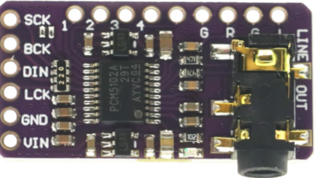
The PCM5102A is a high-performance digital-to-analog converter (DAC) designed for audio applications. It delivers high-resolution audio output with low distortion, making it ideal for high-fidelity audio systems. The component supports a wide range of audio formats, including PCM data, and features a simple interface for seamless integration into audio systems. Its low power consumption and advanced noise suppression make it a popular choice for portable and professional audio devices.
Explore Projects Built with PCM5102A
Use Cirkit Designer to design, explore, and prototype these projects online. Some projects support real-time simulation. Click "Open Project" to start designing instantly!
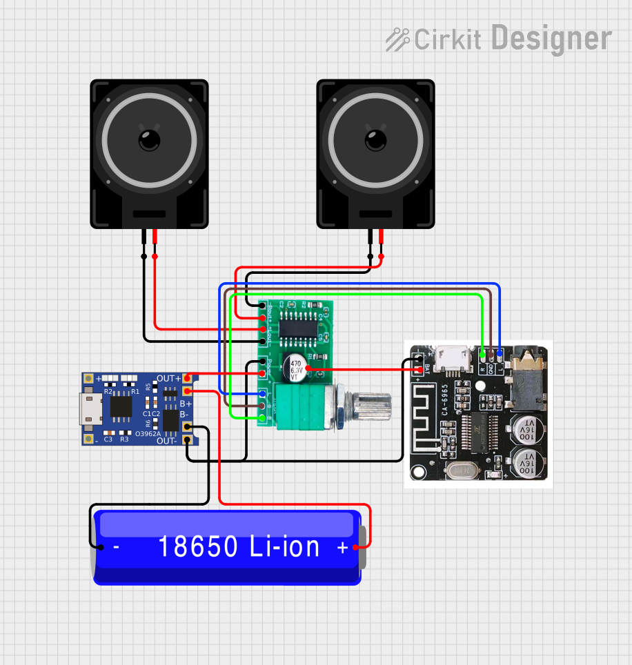
This circuit is a Bluetooth-enabled audio system powered by a rechargeable 18650 Li-ion battery. It includes a TP4056 module for battery charging and protection, a PAM8403 amplifier with volume control to drive two loudspeakers, and a Bluetooth audio receiver to wirelessly receive audio signals.
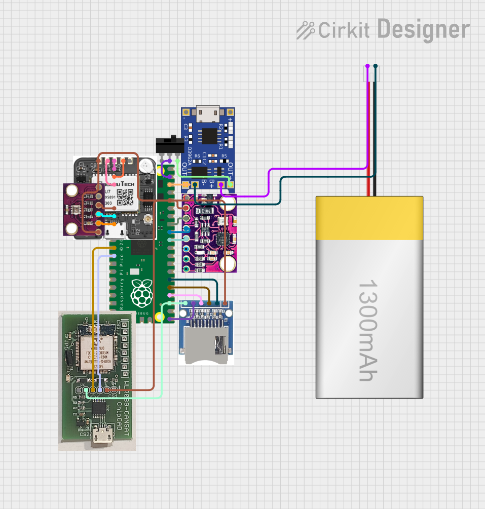
This circuit is a data acquisition and communication system powered by a LiPoly battery and managed by a Raspberry Pi Pico. It includes sensors (BMP280, MPU9250) for environmental data, a GPS module for location tracking, an SD card for data storage, and a WLR089-CanSAT for wireless communication. The TP4056 module handles battery charging, and a toggle switch controls power distribution.
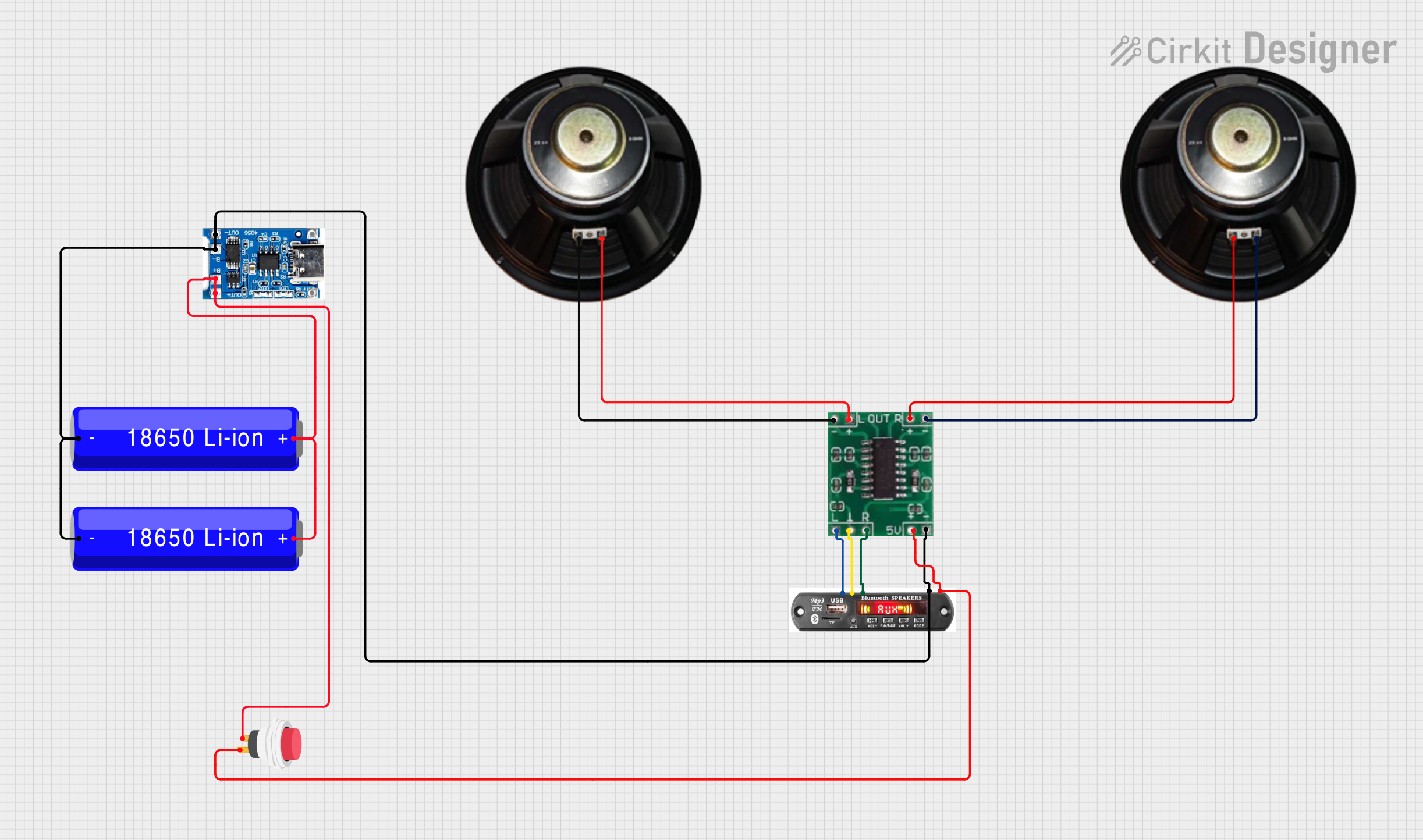
This circuit is a portable audio playback system powered by two 18650 Li-ion batteries, which are charged and protected by a TP4056 module. The MP3 module provides audio signals to a 5V amplifier board, which then drives two speakers. A push switch is used to control the power to the MP3 module and amplifier.
This circuit features an Arduino Mega 2560 microcontroller interfaced with a SIM800L GSM module, two fingerprint scanners, an I2C LCD display, an IR sensor, and a piezo buzzer. Power management is handled by a PowerBoost 1000 Basic Pad USB, a TP4056 charging module, and a Li-ion 18650 battery, with an option to use a Mini AC-DC 110V-230V to 5V 700mA module for direct power supply. The primary functionality appears to be a security system with GSM communication capabilities, biometric access control, and visual/audible feedback.
The PCM5102A offers robust performance and flexibility for audio applications. Below are its key technical specifications:
Parameter
Value
Supply Voltage (VDD)
1.8V to 3.3V
Analog Output Voltage Range
2.1V RMS (typical)
Signal-to-Noise Ratio (SNR)
112 dB (typical)
Total Harmonic Distortion + Noise (THD+N)
-93 dB (typical)
Sampling Rates Supported
8 kHz to 384 kHz
Audio Data Formats
I2S, Left-Justified, Right-Justified
Power Consumption
20 mW (typical)
Package Type
TSSOP-20
Pin Configuration and Descriptions
The PCM5102A comes in a 20-pin TSSOP package. Below is the pin configuration and description:
Pin Number
Pin Name
Description
1
DVDD
Digital power supply (1.8V to 3.3V)
2
DGND
Digital ground
3
SCK
System clock input
4
BCK
Bit clock input for I2S
5
DIN
Digital audio data input
6
LRCK
Left/Right clock input for I2S
7
FMT
Audio format selection
8
XSMT
Soft mute control
9
FLT
Filter response selection
10
VCOM
Common-mode voltage output
11
VOUTL
Left-channel analog output
12
VOUTR
Right-channel analog output
13
AGND
Analog ground
14
AVDD
Analog power supply (3.3V)
15
NC
No connection
16
NC
No connection
17
NC
No connection
18
NC
No connection
19
NC
No connection
20
NC
No connection
Usage Instructions
How to Use the PCM5102A in a Circuit
Power Supply: Connect the digital power supply (DVDD) to a voltage source between 1.8V and 3.3V. Similarly, connect the analog power supply (AVDD) to a 3.3V source. Ensure proper decoupling capacitors are placed near the power pins to reduce noise.
Grounding: Connect DGND and AGND to a common ground plane to minimize noise interference.
Audio Input: Provide the digital audio signal via the I2S interface (DIN, BCK, LRCK). Ensure the audio format matches the configuration set by the FMT pin.
Analog Output: The left and right analog audio signals are available at the VOUTL and VOUTR pins, respectively. These can be connected to an amplifier or directly to headphones/speakers.
Clock Input: Provide a system clock signal to the SCK pin. The clock frequency should match the sampling rate of the audio data.
Important Considerations
Use low-noise power supplies and proper grounding techniques to achieve optimal audio performance.
Configure the FMT pin to select the desired audio format (e.g., I2S, Left-Justified, or Right-Justified).
Use appropriate filtering capacitors on the analog output pins to reduce high-frequency noise.
Avoid leaving unused pins floating; connect them to ground or as specified in the datasheet.
Example: Connecting PCM5102A to Arduino UNO
The PCM5102A can be interfaced with an Arduino UNO using the I2S protocol. Below is an example code snippet to send audio data to the PCM5102A:
#include <I2S.h> // Include the I2S library for Arduino

void setup() {
  // Initialize the I2S interface in master mode
  if (!I2S.begin(I2S_PHILIPS_MODE, 44100, 16)) {
    // Check if I2S initialization failed
    while (1) {
      // Stay in an infinite loop if initialization fails
    }
  }
}

void loop() {
  // Example: Send a simple sine wave to the PCM5102A
  for (int i = 0; i < 360; i++) {
    // Generate a sine wave sample
    int sample = 32767 * sin(i * PI / 180);
    I2S.write(sample); // Send the sample to the DAC
  }
}
Notes:
Ensure the Arduino UNO is configured to output I2S signals on the appropriate pins.
The PCM5102A requires a stable clock signal; consider using an external oscillator if needed.
Troubleshooting and FAQs
Common Issues
No Audio Output
Cause: Incorrect power supply or missing connections.
Solution: Verify all power and ground connections. Check the I2S input signals.
Distorted Audio
Cause: Mismatched audio format or sampling rate.
Solution: Ensure the FMT pin is configured correctly and the sampling rate matches the input data.
High Noise or Hiss
Cause: Poor grounding or noisy power supply.
Solution: Use proper decoupling capacitors and ensure a clean ground plane.
Component Overheating
Cause: Exceeding voltage or current ratings.
Solution: Verify the power supply voltages are within the specified range.
FAQs
Q: Can the PCM5102A handle DSD audio formats?
A: No, the PCM5102A is designed to handle PCM audio formats only.
Q: What is the maximum sampling rate supported?
A: The PCM5102A supports sampling rates up to 384 kHz.
Q: Do I need an external clock source for the PCM5102A?
A: Yes, the PCM5102A requires a stable system clock input on the SCK pin.
Q: Can I connect the PCM5102A directly to headphones?
A: While the PCM5102A provides analog output, it is recommended to use an amplifier for driving headphones or speakers.

 Open Project in Cirkit Designer