How to Use l293d driver shield: Examples, Pinouts, and Specs
Introduction
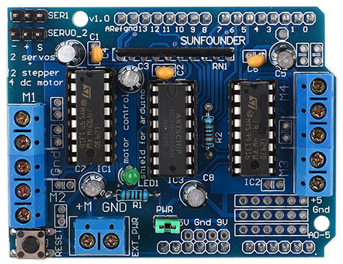
The L293D Motor Driver Shield is an expansion board designed to drive inductive loads such as relays, solenoids, DC, and stepper motors. It lets you drive two DC motors with your Arduino board, controlling the speed and direction of each one independently. The shield is based on the L293D motor driver IC which provides bidirectional drive currents of up to 600mA at voltages from 4.5V to 36V. It is compatible with a wide range of Arduino boards and can be stacked with other shields.
Explore Projects Built with l293d driver shield
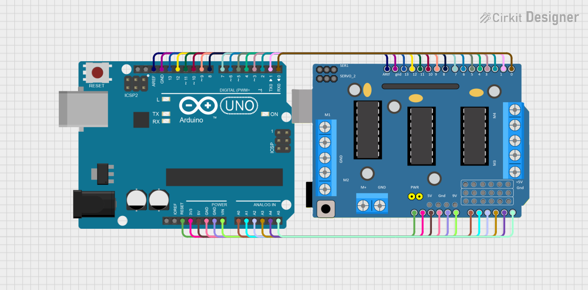
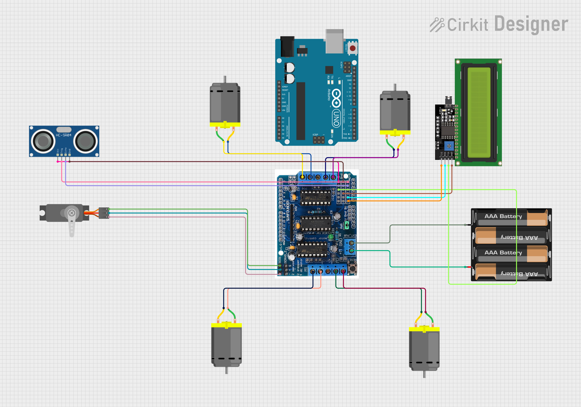
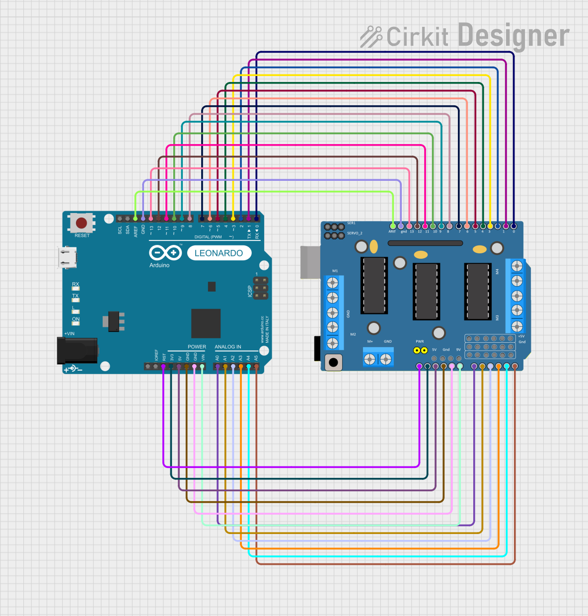

Explore Projects Built with l293d driver shield
Common Applications and Use Cases
- Robotics
- CNC machines
- Automated machinery
- Hobbyist projects involving motor control
Technical Specifications
Key Technical Details
- Motor driver IC: L293D
- Motor voltage: 4.5V to 36V
- Motor current: Up to 600mA per channel (1.2A peak)
- Logic voltage: 5V (from Arduino board)
- Logic current: 0 to 36mA
Pin Configuration and Descriptions
| Pin Number | Function | Description |
|---|---|---|
| 1-2 | Motor A | Connects to the terminals of the first DC motor. |
| 3-4 | Motor B | Connects to the terminals of the second DC motor. |
| 5-6 | Power Supply (V+) | External power supply for motors (4.5V to 36V). |
| 7 | Ground (GND) | Common ground for logic and motor power. |
| 8-9 | Direction Control | Controls the direction of the motors. |
| 10-11 | Speed Control | Controls the speed of the motors (PWM). |
| 12 | Enable Motor A | Enables or disables Motor A. |
| 13 | Enable Motor B | Enables or disables Motor B. |
Usage Instructions
How to Use the Component in a Circuit
Connecting Motors:
- Connect the terminals of the DC motors to the Motor A and Motor B screw terminals on the shield.
Power Supply:
- Provide an external power supply to the Power Supply (V+) pins if the motors require more voltage than the Arduino board can provide.
Control Connections:
- Use the Direction Control and Speed Control pins to interface with the Arduino board for controlling the direction and speed of the motors.
Important Considerations and Best Practices
- Ensure that the external power supply voltage and current do not exceed the shield's maximum ratings.
- Use PWM (Pulse Width Modulation) on the Speed Control pins to vary the speed of the motors.
- Always connect the ground of the motor power supply to the Arduino's ground.
Example Code for Arduino UNO
#include <AFMotor.h>

AF_DCMotor motor(4); // Create motor #4

void setup() {
  motor.setSpeed(200); // Set the speed to 200/255
}

void loop() {
  motor.run(FORWARD); // Turn the motor forward
  delay(1000);        // Run for 1 second
  motor.run(BACKWARD); // Turn the motor backward
  delay(1000);        // Run for 1 second
  motor.run(RELEASE); // Stop the motor
  delay(1000);        // Wait for 1 second
}
Troubleshooting and FAQs
Common Issues Users Might Face
- Motor not running: Check the power supply and connections to the motor.
- Insufficient torque: Ensure the power supply can deliver enough current for the motor.
- Overheating: Avoid running the motor at high currents for extended periods.
Solutions and Tips for Troubleshooting
- Verify that all connections are secure and correct.
- Ensure that the external power supply is within the recommended voltage range and can provide sufficient current.
- Use a multimeter to check for continuity and proper voltage levels at the motor terminals.
FAQs
Q: Can I control a stepper motor with this shield? A: Yes, the L293D shield can be used to control a bipolar stepper motor.
Q: What is the maximum current the L293D shield can handle? A: The shield can handle up to 600mA per channel continuously, with peak currents of 1.2A.
Q: Can I stack other shields on top of the L293D shield? A: Yes, the shield is designed to be stackable with other Arduino shields.
Q: Do I need an external power supply? A: An external power supply is necessary if the motor requires more voltage or current than the Arduino board can provide.
Q: How do I control the speed of the motors? A: You can control the speed by applying PWM signals to the Speed Control pins.