Cirkit Designer Logo
Cirkit Designer
Your all-in-one circuit design IDE
Home / 
Component Documentation

How to Use sound sensor: Examples, Pinouts, and Specs

Image of sound sensor
Cirkit Designer LogoDesign with sound sensor in Cirkit Designer

Introduction

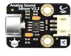
The DFRobot Sound Sensor is a compact and efficient module designed to detect sound levels and convert them into an electrical signal. This sensor is ideal for applications such as sound detection, voice recognition, and noise monitoring. It is widely used in projects that require audio-based input, such as interactive systems, smart devices, and environmental monitoring.

The sensor is easy to integrate into microcontroller-based systems, including Arduino, Raspberry Pi, and other development platforms. Its adjustable sensitivity and simple interface make it suitable for both beginners and advanced users.

Explore Projects Built with sound sensor

Use Cirkit Designer to design, explore, and prototype these projects online. Some projects support real-time simulation. Click "Open Project" to start designing instantly!
Arduino UNO-Based Multi-Sensor Health and Environmental Monitoring System with Bluetooth Connectivity
Image of Sleep Appnea Monitoring System: A project utilizing sound sensor in a practical application
This is a multi-functional sensor and communication circuit built around an Arduino UNO. It is designed to collect environmental and health-related data, process and respond to voice commands, and communicate wirelessly. Output feedback is provided through LEDs and a buzzer.
Cirkit Designer LogoOpen Project in Cirkit Designer
Arduino Uno R3-Based Environmental Monitoring System with Sound Detection and Data Logging
Image of sound: A project utilizing sound sensor in a practical application
This circuit is designed to interface with multiple sensors, including sound sensors, an ultrasonic sensor (HC-SR04), and gas sensors (MQ135), to an Arduino Uno R3 for data acquisition and processing. The Arduino communicates with an I2C LCD screen for data display and a micro SD card module for data logging. The circuit likely serves as a multi-sensor environmental monitoring system, capable of detecting sound, distance, and gas levels, displaying information, and storing data.
Cirkit Designer LogoOpen Project in Cirkit Designer
Arduino Uno R3 Multi-Sensor Monitoring System with Data Logging and Audio Alerts
Image of sound2: A project utilizing sound sensor in a practical application
This circuit is designed for environmental monitoring and data logging. It features an Arduino Uno R3 as the central controller, interfaced with multiple sensors including sound sensors, MQ135 gas sensors for air quality, and an HC-SR04 ultrasonic sensor for distance measurement. The data from these sensors can be displayed on an I2C LCD screen and logged onto a micro SD card, while the speakers are likely used for audible alerts or feedback.
Cirkit Designer LogoOpen Project in Cirkit Designer
Arduino Uno R3 Sound-Activated Relay Switch
Image of clap activated lamp: A project utilizing sound sensor in a practical application
This circuit is designed to detect sound through a sound sensor and trigger a relay based on the detected sound signal. The sound sensor is powered by the Arduino Uno R3 and sends a digital signal to one of the Arduino's digital pins when sound is detected. The Arduino then controls the relay, which can switch a separate circuit that could be connected to its normally open (NO) or normally closed (NC) contacts.
Cirkit Designer LogoOpen Project in Cirkit Designer

Explore Projects Built with sound sensor

Use Cirkit Designer to design, explore, and prototype these projects online. Some projects support real-time simulation. Click "Open Project" to start designing instantly!
Image of Sleep Appnea Monitoring System: A project utilizing sound sensor in a practical application
Arduino UNO-Based Multi-Sensor Health and Environmental Monitoring System with Bluetooth Connectivity
This is a multi-functional sensor and communication circuit built around an Arduino UNO. It is designed to collect environmental and health-related data, process and respond to voice commands, and communicate wirelessly. Output feedback is provided through LEDs and a buzzer.
Cirkit Designer LogoOpen Project in Cirkit Designer
Image of sound: A project utilizing sound sensor in a practical application
Arduino Uno R3-Based Environmental Monitoring System with Sound Detection and Data Logging
This circuit is designed to interface with multiple sensors, including sound sensors, an ultrasonic sensor (HC-SR04), and gas sensors (MQ135), to an Arduino Uno R3 for data acquisition and processing. The Arduino communicates with an I2C LCD screen for data display and a micro SD card module for data logging. The circuit likely serves as a multi-sensor environmental monitoring system, capable of detecting sound, distance, and gas levels, displaying information, and storing data.
Cirkit Designer LogoOpen Project in Cirkit Designer
Image of sound2: A project utilizing sound sensor in a practical application
Arduino Uno R3 Multi-Sensor Monitoring System with Data Logging and Audio Alerts
This circuit is designed for environmental monitoring and data logging. It features an Arduino Uno R3 as the central controller, interfaced with multiple sensors including sound sensors, MQ135 gas sensors for air quality, and an HC-SR04 ultrasonic sensor for distance measurement. The data from these sensors can be displayed on an I2C LCD screen and logged onto a micro SD card, while the speakers are likely used for audible alerts or feedback.
Cirkit Designer LogoOpen Project in Cirkit Designer
Image of clap activated lamp: A project utilizing sound sensor in a practical application
Arduino Uno R3 Sound-Activated Relay Switch
This circuit is designed to detect sound through a sound sensor and trigger a relay based on the detected sound signal. The sound sensor is powered by the Arduino Uno R3 and sends a digital signal to one of the Arduino's digital pins when sound is detected. The Arduino then controls the relay, which can switch a separate circuit that could be connected to its normally open (NO) or normally closed (NC) contacts.
Cirkit Designer LogoOpen Project in Cirkit Designer

Technical Specifications

  • Manufacturer: DFRobot
  • Operating Voltage: 3.3V to 5V
  • Output Type: Analog and Digital
  • Sensitivity Adjustment: Potentiometer
  • Dimensions: 22mm x 30mm
  • Weight: ~5g

Pin Configuration and Descriptions

The DFRobot Sound Sensor has a 3-pin interface for easy connection to microcontrollers. Below is the pin configuration:

Pin Name Description
1 VCC Power supply pin. Connect to 3.3V or 5V.
2 GND Ground pin. Connect to the ground of the circuit.
3 OUT Signal output pin. Outputs an analog voltage proportional to the sound level.

Usage Instructions

Connecting the Sound Sensor

  1. Power the Sensor: Connect the VCC pin to a 3.3V or 5V power source and the GND pin to the ground.
  2. Signal Output: Connect the OUT pin to an analog input pin on your microcontroller (e.g., Arduino A0).
  3. Adjust Sensitivity: Use the onboard potentiometer to adjust the sensitivity of the sensor. Turn clockwise to increase sensitivity and counterclockwise to decrease it.

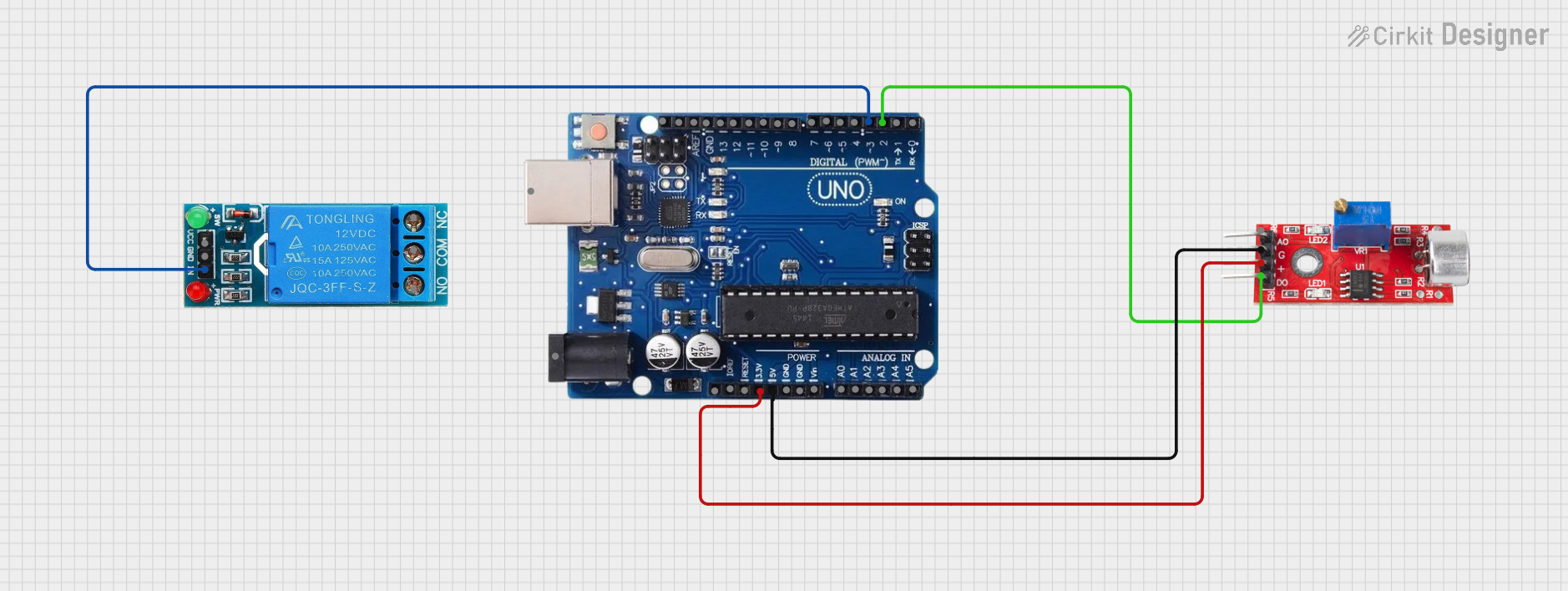
Example Circuit with Arduino UNO

Below is an example of how to connect the DFRobot Sound Sensor to an Arduino UNO:

  • VCC → Arduino 5V
  • GND → Arduino GND
  • OUT → Arduino A0

Example Code for Arduino UNO

The following code reads the analog signal from the sound sensor and prints the sound level to the Serial Monitor.

// Define the analog pin connected to the sound sensor
const int soundSensorPin = A0;

void setup() {
  // Initialize the serial communication at 9600 baud rate
  Serial.begin(9600);
}

void loop() {
  // Read the analog value from the sound sensor
  int soundLevel = analogRead(soundSensorPin);

  // Print the sound level to the Serial Monitor
  Serial.print("Sound Level: ");
  Serial.println(soundLevel);

  // Add a small delay to avoid flooding the Serial Monitor
  delay(100);
}

Best Practices

  • Avoid placing the sensor near high-frequency noise sources, as this may interfere with its readings.
  • Use a stable power supply to ensure accurate measurements.
  • Adjust the sensitivity carefully to match the requirements of your application.

Troubleshooting and FAQs

Common Issues

  1. No Output Signal

    • Cause: Incorrect wiring or insufficient power supply.
    • Solution: Double-check the connections and ensure the sensor is powered with 3.3V or 5V.
  2. Inconsistent Readings

    • Cause: Environmental noise or unstable power supply.
    • Solution: Place the sensor in a quieter environment and use a decoupling capacitor across the power pins.
  3. Sensor Not Sensitive Enough

    • Cause: Sensitivity not adjusted properly.
    • Solution: Use the onboard potentiometer to increase the sensitivity.

FAQs

Q: Can this sensor detect specific sounds like clapping or voice commands?
A: The sensor detects general sound levels and cannot differentiate between specific sounds. For specific sound recognition, additional signal processing or machine learning algorithms are required.

Q: Can I use this sensor with a Raspberry Pi?
A: Yes, the sensor can be connected to a Raspberry Pi. However, since the Raspberry Pi does not have analog input pins, you will need an ADC (Analog-to-Digital Converter) to read the analog output.

Q: What is the maximum distance for sound detection?
A: The detection range depends on the sensitivity setting and the loudness of the sound source. Typically, it works best within a few meters.

By following this documentation, you can effectively integrate the DFRobot Sound Sensor into your projects and troubleshoot common issues with ease.