How to Use Mini Digital Volt/Ammeter: Examples, Pinouts, and Specs
Introduction
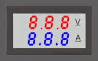
The Mini Digital Volt/Ammeter is a compact, dual-function electronic device designed to measure and display both voltage and current in an electrical circuit. This component is essential for monitoring the health and performance of electronic systems, making it a valuable tool for hobbyists, technicians, and engineers alike. Common applications include power supply monitoring, battery charging systems, and any project where real-time voltage and current readings are beneficial.
Explore Projects Built with Mini Digital Volt/Ammeter

Explore Projects Built with Mini Digital Volt/Ammeter
Technical Specifications
Key Technical Details
- Voltage Measurement Range: Typically 0-100V DC
- Current Measurement Range: Typically 0-10A DC
- Display Type: LED, often red for voltage and blue for current
- Accuracy: ±1% (varies by model)
- Supply Voltage: Typically 4.5-30V DC
- Operating Temperature: -10°C to 65°C
Pin Configuration and Descriptions
| Pin Number | Description | Notes |
|---|---|---|
| 1 | Power Supply (+) | 4.5-30V DC |
| 2 | Ground (-) | Common ground for power and signal |
| 3 | Voltage Measurement Input (+) | 0-100V DC |
| 4 | Current Measurement Input (Shunt) | Connect in series with load |
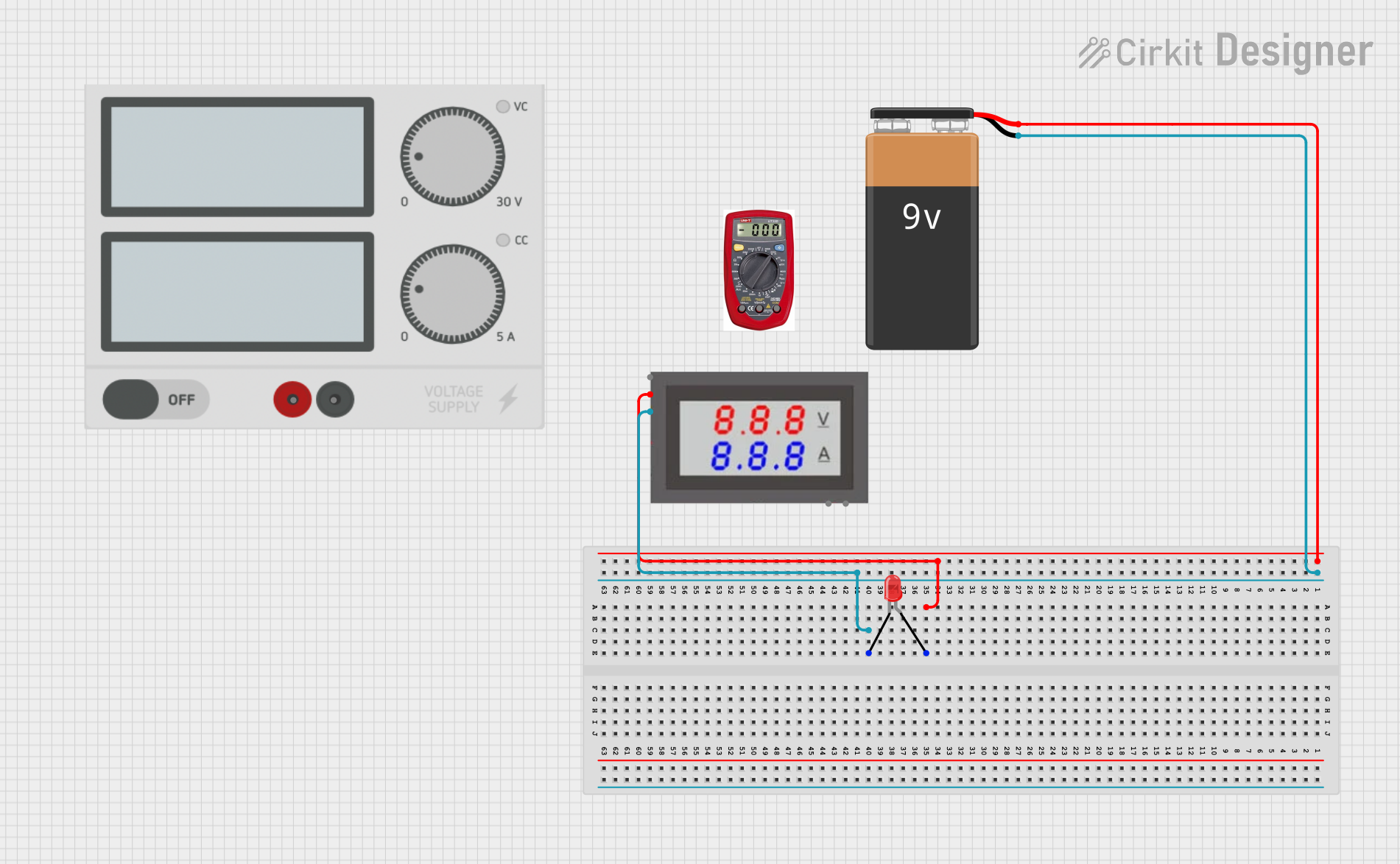
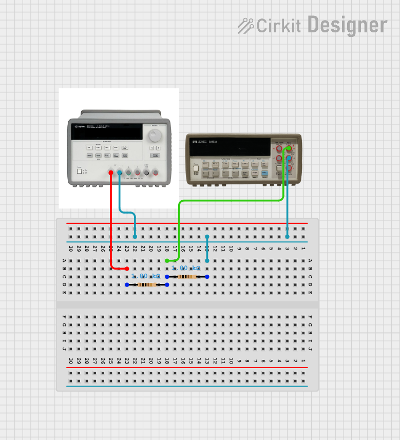
Usage Instructions
How to Use the Component in a Circuit
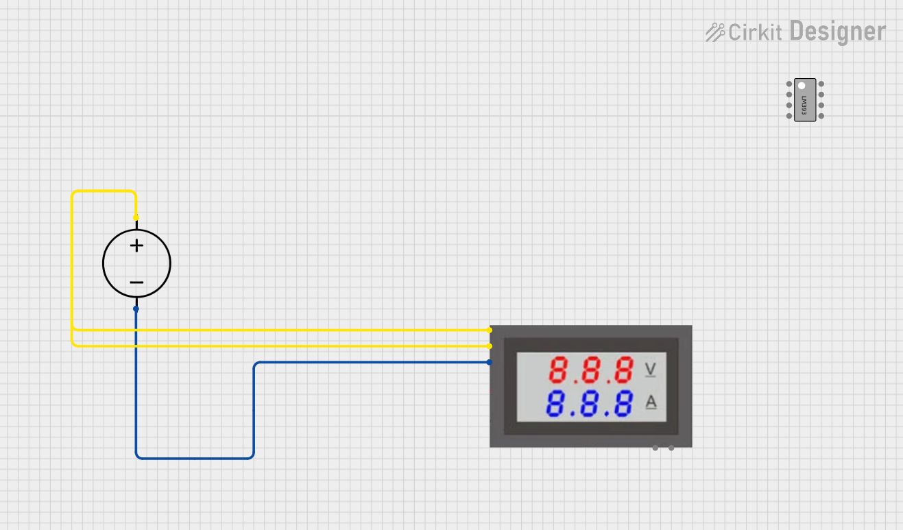
Powering the Device:
- Connect the positive supply voltage to Pin 1.
- Connect the ground to Pin 2.
Measuring Voltage:
- Connect the positive terminal of the circuit to be measured to Pin 3.
- Ensure the negative terminal of the circuit is common with the device ground.
Measuring Current:
- Insert the device in series with the load using Pin 4.
- The current flows through an internal shunt resistor, allowing the device to measure the current without an external shunt.
Important Considerations and Best Practices
- Isolation: Ensure that the power supply for the voltmeter/ammeter is isolated from the high currents being measured to prevent damage.
- Calibration: Some models may require calibration for accurate readings. Follow the manufacturer's instructions for calibration.
- Wiring: Use appropriate gauge wires for the current being measured to prevent overheating and ensure accurate readings.
- Safety: Always follow electrical safety protocols when working with live circuits.
Troubleshooting and FAQs
Common Issues
- Inaccurate Readings: Check for proper calibration, ensure that the connections are secure, and verify that the component is within its specified measurement range.
- No Display: Ensure the device is properly powered and that the supply voltage is within the specified range.
- Fluctuating Readings: Check for loose connections or interference from nearby high-current wires.
Solutions and Tips
- Calibration: If the device supports calibration, adjust it according to the provided instructions.
- Connection Check: Re-secure all connections and ensure that the wiring is intact and not damaged.
- Interference: Route measurement wires away from high-current paths to minimize electromagnetic interference.
FAQs
Q: Can the Mini Digital Volt/Ammeter measure AC voltage or current? A: Typically, these devices are designed for DC measurements only. Check the specifications for AC capabilities.
Q: Is it necessary to use an external shunt with this device? A: No, most Mini Digital Volt/Ammeters have a built-in shunt for current measurement.
Q: How do I reset the calibration if I make a mistake? A: Refer to the manufacturer's instructions. Some devices have a reset function, while others may require a specific procedure to re-enter calibration mode.
Example Arduino UNO Connection and Code
// Example code for interfacing a Mini Digital Volt/Ammeter with an Arduino UNO
// This code assumes the voltmeter/ammeter requires a digital signal to calibrate or reset.

#include <Arduino.h>

const int calibrationPin = 7; // Connect to the calibration/reset pin if available

void setup() {
  pinMode(calibrationPin, OUTPUT);
  Serial.begin(9600);
}

void loop() {
  // Example function to trigger calibration
  calibrateMeter();
  // Add your main code here
}

void calibrateMeter() {
  digitalWrite(calibrationPin, HIGH); // Send a high signal to trigger calibration
  delay(100);                         // Wait for 100 milliseconds
  digitalWrite(calibrationPin, LOW);  // Return to low signal
  Serial.println("Calibration signal sent.");
  delay(5000);                        // Wait for 5 seconds before next calibration
}
Note: The above code is a generic template and may not apply to all Mini Digital Volt/Ammeters. Always refer to the specific datasheet for your model for accurate interfacing and control.