How to Use BUCK: Examples, Pinouts, and Specs
Introduction
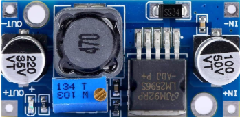
The BUCK DC/DC converter, manufactured by HUAREW, is a highly efficient DC-DC step-down voltage regulator. It is designed to convert a higher input voltage to a lower output voltage while maintaining high efficiency and stepping up the current. This component is widely used in power management systems, battery-powered devices, and embedded systems where efficient voltage regulation is critical.
Explore Projects Built with BUCK


Explore Projects Built with BUCK
Common Applications
- Power supply for microcontrollers and embedded systems
- Battery charging circuits
- LED drivers
- Industrial automation systems
- Consumer electronics (e.g., portable devices, laptops)
Technical Specifications
The following table outlines the key technical specifications of the BUCK DC/DC converter:
| Parameter | Value |
|---|---|
| Input Voltage Range | 4.5V to 40V |
| Output Voltage Range | 1.2V to 36V |
| Output Current | Up to 3A |
| Efficiency | Up to 95% |
| Switching Frequency | 150 kHz |
| Operating Temperature | -40°C to +85°C |
| Package Type | TO-220 or SMD (varies by model) |
Pin Configuration
The BUCK DC/DC converter typically has the following pin configuration:
| Pin Number | Pin Name | Description |
|---|---|---|
| 1 | VIN | Input voltage (connect to the higher voltage source) |
| 2 | GND | Ground (common ground for input and output) |
| 3 | VOUT | Output voltage (connect to the load) |
| 4 | EN | Enable pin (used to turn the converter on/off) |
| 5 | FB | Feedback pin (used for voltage regulation) |
Usage Instructions
How to Use the BUCK DC/DC Converter in a Circuit
Connect the Input Voltage (VIN):
Attach the input voltage source to the VIN pin. Ensure the input voltage is within the specified range (4.5V to 40V).Connect the Ground (GND):
Connect the GND pin to the common ground of the circuit.Connect the Output Voltage (VOUT):
Attach the load to the VOUT pin. The output voltage will be regulated to the desired level.Set the Output Voltage (Optional):
If the converter has an adjustable output, use a resistor divider network connected to the FB pin to set the desired output voltage.Enable the Converter (Optional):
Use the EN pin to enable or disable the converter. Pull the EN pin high to enable the converter or low to disable it.
Important Considerations
- Input Voltage: Ensure the input voltage is always higher than the desired output voltage.
- Heat Dissipation: Use a heatsink or proper ventilation if the converter operates at high currents to prevent overheating.
- Capacitors: Place input and output capacitors close to the converter to reduce noise and improve stability.
- Inductor Selection: Choose an appropriate inductor value based on the desired output current and voltage ripple.
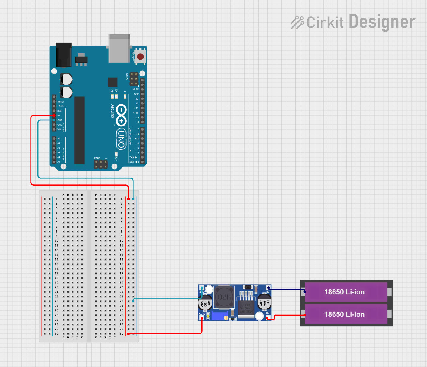
Example: Using BUCK DC/DC with Arduino UNO
The following example demonstrates how to use the BUCK DC/DC converter to power an Arduino UNO with a 12V input source and regulate it to 5V.
Circuit Connections
- Connect the 12V input source to the VIN pin of the BUCK converter.
- Connect the GND pin of the BUCK converter to the Arduino's GND.
- Connect the VOUT pin of the BUCK converter to the Arduino's 5V pin.
Arduino Code
// Example code to blink an LED using Arduino UNO powered by BUCK DC/DC converter

const int ledPin = 13; // Pin connected to the onboard LED

void setup() {
  pinMode(ledPin, OUTPUT); // Set the LED pin as an output
}

void loop() {
  digitalWrite(ledPin, HIGH); // Turn the LED on
  delay(1000);                // Wait for 1 second
  digitalWrite(ledPin, LOW);  // Turn the LED off
  delay(1000);                // Wait for 1 second
}
Troubleshooting and FAQs
Common Issues and Solutions
No Output Voltage:
- Cause: The EN pin is not connected or is pulled low.
- Solution: Ensure the EN pin is pulled high to enable the converter.
Output Voltage is Incorrect:
- Cause: Incorrect resistor values in the feedback network.
- Solution: Verify and adjust the resistor divider network connected to the FB pin.
Overheating:
- Cause: High current draw or insufficient cooling.
- Solution: Use a heatsink or improve ventilation around the converter.
Noise or Instability:
- Cause: Missing or improperly placed capacitors.
- Solution: Add input and output capacitors close to the converter pins.
FAQs
Q: Can the BUCK DC/DC converter handle reverse polarity on the input?
A: No, the converter does not have built-in reverse polarity protection. Use a diode in series with the input to prevent damage.
Q: What is the maximum efficiency of the BUCK DC/DC converter?
A: The converter can achieve up to 95% efficiency under optimal conditions.
Q: Can I use the BUCK DC/DC converter to step up voltage?
A: No, the BUCK DC/DC converter is designed only for step-down (buck) voltage regulation. For step-up applications, use a boost converter.
Q: How do I calculate the output voltage for an adjustable BUCK converter?
A: Use the formula:
[
V_{OUT} = V_{REF} \times \left(1 + \frac{R1}{R2}\right)
]
where ( V_{REF} ) is the reference voltage (typically 1.25V), and ( R1 ) and ( R2 ) are the feedback resistors.
This concludes the documentation for the HUAREW BUCK DC/DC converter.