Cirkit Designer Logo
Cirkit Designer
Your all-in-one circuit design IDE
Home / 
Component Documentation

How to Use Touch sensor With LED: Examples, Pinouts, and Specs

Image of Touch sensor With LED
Cirkit Designer LogoDesign with Touch sensor With LED in Cirkit Designer

Introduction

The TTP233H-HA6 touch sensor, manufactured by Tontek Design Technology, is a capacitive touch sensor designed to detect physical touch and activate an LED indicator. This component is widely used in interactive devices, user interfaces, and touch-based control systems. It offers a simple and reliable way to replace traditional mechanical buttons with a touch-sensitive interface.

Explore Projects Built with Touch sensor With LED

Use Cirkit Designer to design, explore, and prototype these projects online. Some projects support real-time simulation. Click "Open Project" to start designing instantly!
Arduino UNO Touch-Activated LED Circuit
Image of ARDUINO LED ON WITH TOUCH SENSOR WIRING: A project utilizing Touch sensor With LED in a practical application
This circuit uses an Arduino UNO to control an LED based on input from a touch sensor. The touch sensor is connected to the Arduino's digital pin D2, and the LED is connected to digital pin D13, allowing the Arduino to turn the LED on or off in response to touch input.
Cirkit Designer LogoOpen Project in Cirkit Designer
Arduino-Controlled Multi-Touch Sensor Interface with Solar Charging and OLED Display
Image of module 1 & 3: A project utilizing Touch sensor With LED in a practical application
This circuit appears to be a touch-activated lighting system with voltage monitoring capabilities. It includes multiple touch sensors interfaced with an Arduino UNO to control red LEDs and a multi-color LED, with resistors for current limiting. The system also features a solar panel connected to a charging module for an 18650 Li-Ion battery, which powers the circuit, and a voltage sensor to monitor the battery voltage, with an OLED display for visual output.
Cirkit Designer LogoOpen Project in Cirkit Designer
Arduino 101 Based Touch-Controlled LED Matrix with DHT22 Sensor Integration
Image of PROJECT TOUCH SENSOR: A project utilizing Touch sensor With LED in a practical application
This circuit features an Arduino 101 microcontroller connected to a touch sensor, an 8x8 LED matrix, and a DHT22 temperature and humidity sensor. The Arduino provides power to all components and interfaces with the touch sensor via a digital I/O pin and the DHT22 sensor via another digital I/O pin. It controls the 8x8 LED matrix using SPI communication, with dedicated pins for data, clock, and chip select.
Cirkit Designer LogoOpen Project in Cirkit Designer
Arduino UNO Controlled Touch-Activated LED and Buzzer System
Image of touch sensor controlled led: A project utilizing Touch sensor With LED in a practical application
This circuit features an Arduino UNO microcontroller connected to a touch sensor, a red LED with a series resistor, and a buzzer. The touch sensor's output is connected to digital pin D2 of the Arduino, which likely controls the LED connected to pin D13 and the buzzer connected to pin D5 based on touch input. The LED's anode is directly connected to the Arduino, while its cathode is connected through a 220-ohm resistor, and the buzzer's other pin is grounded, suggesting that both are controlled via digital output pins for signaling or user interaction.
Cirkit Designer LogoOpen Project in Cirkit Designer

Explore Projects Built with Touch sensor With LED

Use Cirkit Designer to design, explore, and prototype these projects online. Some projects support real-time simulation. Click "Open Project" to start designing instantly!
Image of ARDUINO LED ON WITH TOUCH SENSOR WIRING: A project utilizing Touch sensor With LED in a practical application
Arduino UNO Touch-Activated LED Circuit
This circuit uses an Arduino UNO to control an LED based on input from a touch sensor. The touch sensor is connected to the Arduino's digital pin D2, and the LED is connected to digital pin D13, allowing the Arduino to turn the LED on or off in response to touch input.
Cirkit Designer LogoOpen Project in Cirkit Designer
Image of module 1 & 3: A project utilizing Touch sensor With LED in a practical application
Arduino-Controlled Multi-Touch Sensor Interface with Solar Charging and OLED Display
This circuit appears to be a touch-activated lighting system with voltage monitoring capabilities. It includes multiple touch sensors interfaced with an Arduino UNO to control red LEDs and a multi-color LED, with resistors for current limiting. The system also features a solar panel connected to a charging module for an 18650 Li-Ion battery, which powers the circuit, and a voltage sensor to monitor the battery voltage, with an OLED display for visual output.
Cirkit Designer LogoOpen Project in Cirkit Designer
Image of PROJECT TOUCH SENSOR: A project utilizing Touch sensor With LED in a practical application
Arduino 101 Based Touch-Controlled LED Matrix with DHT22 Sensor Integration
This circuit features an Arduino 101 microcontroller connected to a touch sensor, an 8x8 LED matrix, and a DHT22 temperature and humidity sensor. The Arduino provides power to all components and interfaces with the touch sensor via a digital I/O pin and the DHT22 sensor via another digital I/O pin. It controls the 8x8 LED matrix using SPI communication, with dedicated pins for data, clock, and chip select.
Cirkit Designer LogoOpen Project in Cirkit Designer
Image of touch sensor controlled led: A project utilizing Touch sensor With LED in a practical application
Arduino UNO Controlled Touch-Activated LED and Buzzer System
This circuit features an Arduino UNO microcontroller connected to a touch sensor, a red LED with a series resistor, and a buzzer. The touch sensor's output is connected to digital pin D2 of the Arduino, which likely controls the LED connected to pin D13 and the buzzer connected to pin D5 based on touch input. The LED's anode is directly connected to the Arduino, while its cathode is connected through a 220-ohm resistor, and the buzzer's other pin is grounded, suggesting that both are controlled via digital output pins for signaling or user interaction.
Cirkit Designer LogoOpen Project in Cirkit Designer

Common Applications

  • Touch-sensitive switches for home automation
  • Interactive displays and control panels
  • Consumer electronics (e.g., lamps, appliances)
  • Prototyping and DIY projects
  • Embedded systems with touch-based input

Technical Specifications

The TTP233H-HA6 touch sensor is a low-power, high-sensitivity device with the following key specifications:

Parameter Value
Operating Voltage 2.0V to 5.5V
Operating Current < 8µA (at 3V, no load)
Response Time ~60ms (fast mode)
Output Type Active Low (default)
Touch Sensitivity Adjustable via external capacitor
Operating Temperature -40°C to +85°C
LED Indicator Built-in

Pin Configuration and Descriptions

The TTP233H-HA6 is typically available in a 6-pin SOT-23-6 package. Below is the pinout and description:

Pin Name Description
1 VDD Power supply input (2.0V to 5.5V). Connect to the positive terminal of the power source.
2 OUT Output pin. Goes LOW when touch is detected. Can drive an LED or interface with a microcontroller.
3 AHLB Active High/Low selection. Connect to GND for active LOW output (default).
4 MODE Mode selection. Connect to GND for fast mode or VDD for low-power mode.
5 VSS Ground. Connect to the negative terminal of the power source.
6 TPAD Touchpad input. Connect to a conductive touch surface (e.g., copper pad).

Usage Instructions

How to Use the Component in a Circuit

  1. Power Supply: Connect the VDD pin to a 3.3V or 5V power source and the VSS pin to ground.
  2. Touchpad Connection: Attach a conductive material (e.g., copper foil) to the TPAD pin to act as the touch-sensitive surface.
  3. Output Connection: Connect the OUT pin to an LED (with a current-limiting resistor) or to a microcontroller input pin.
  4. Mode Selection:
    • For fast response, connect the MODE pin to ground.
    • For low-power operation, connect the MODE pin to VDD.
  5. Active Output Selection:
    • For active LOW output (default), connect the AHLB pin to ground.
    • For active HIGH output, connect the AHLB pin to VDD.

Example Circuit

Below is a simple circuit to use the TTP233H-HA6 with an LED indicator:

VDD (3.3V/5V) ----+----[10kΩ]---- MODE (GND for fast mode)
                  |
                  +---- AHLB (GND for active LOW)
                  |
                  +---- VDD Pin (Power Input)
                  |
                 [LED]----[330Ω]---- OUT Pin
                  |
                 GND ---- VSS Pin

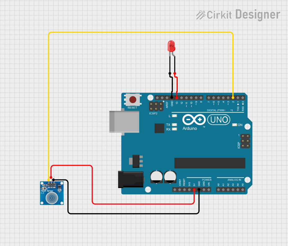
Using with Arduino UNO

The TTP233H-HA6 can be easily interfaced with an Arduino UNO. The OUT pin can be connected to a digital input pin on the Arduino to detect touch events. Below is an example Arduino sketch:

// Define the pin connected to the TTP233H-HA6 OUT pin
const int touchPin = 2;  // Digital pin 2
const int ledPin = 13;   // Built-in LED on Arduino UNO

void setup() {
  pinMode(touchPin, INPUT);  // Set touchPin as input
  pinMode(ledPin, OUTPUT);   // Set ledPin as output
  Serial.begin(9600);        // Initialize serial communication
}

void loop() {
  int touchState = digitalRead(touchPin);  // Read the touch sensor state

  if (touchState == LOW) {  // Active LOW output indicates touch detected
    digitalWrite(ledPin, HIGH);  // Turn on the LED
    Serial.println("Touch detected!");
  } else {
    digitalWrite(ledPin, LOW);   // Turn off the LED
  }

  delay(100);  // Small delay for stability
}

Important Considerations and Best Practices

  • Touchpad Design: Use a smooth, conductive material for the touchpad to ensure reliable touch detection.
  • Debouncing: If the sensor output is noisy, consider adding software debouncing in your microcontroller code.
  • Power Supply: Ensure a stable power supply to avoid erratic behavior.
  • Output Load: Do not exceed the maximum current rating of the OUT pin. Use a current-limiting resistor for LEDs.

Troubleshooting and FAQs

Common Issues and Solutions

  1. Sensor Not Responding:

    • Verify the power supply connections to VDD and VSS.
    • Check the touchpad connection to the TPAD pin.
    • Ensure the MODE and AHLB pins are correctly configured.
  2. False Touch Detection:

    • Reduce noise by adding a decoupling capacitor (e.g., 0.1µF) between VDD and VSS.
    • Ensure the touchpad is not exposed to excessive electrical interference.
  3. LED Not Lighting Up:

    • Check the LED polarity and the current-limiting resistor value.
    • Verify the connection between the OUT pin and the LED.
  4. Intermittent Behavior:

    • Ensure a stable power supply and proper grounding.
    • Check for loose connections in the circuit.

FAQs

Q: Can I use the TTP233H-HA6 with a 3.3V microcontroller?
A: Yes, the TTP233H-HA6 operates within a voltage range of 2.0V to 5.5V, making it compatible with 3.3V systems.

Q: How do I adjust the touch sensitivity?
A: The touch sensitivity can be adjusted by changing the value of the external capacitor connected to the TPAD pin. Refer to the manufacturer's datasheet for recommended values.

Q: Can I use multiple TTP233H-HA6 sensors in the same circuit?
A: Yes, but ensure each sensor has its own touchpad and does not share the same conductive surface to avoid interference.

Q: What is the maximum distance for touch detection?
A: The detection distance depends on the size and material of the touchpad. Larger conductive surfaces typically allow for greater detection distances.