
How to Use Header 3: Examples, Pinouts, and Specs
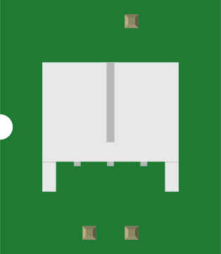
 Design with Header 3 in Cirkit Designer
Introduction
A Header 3 is a type of connector used in electronic circuits to facilitate the connection of multiple wires or cables. It typically features three pins, allowing for secure and organized connections. These connectors are widely used in prototyping, PCB designs, and modular electronic systems. Header 3 connectors are versatile and can be used for both signal and power connections, making them a staple in many electronic projects.
Explore Projects Built with Header 3
 Open Project in Cirkit Designer
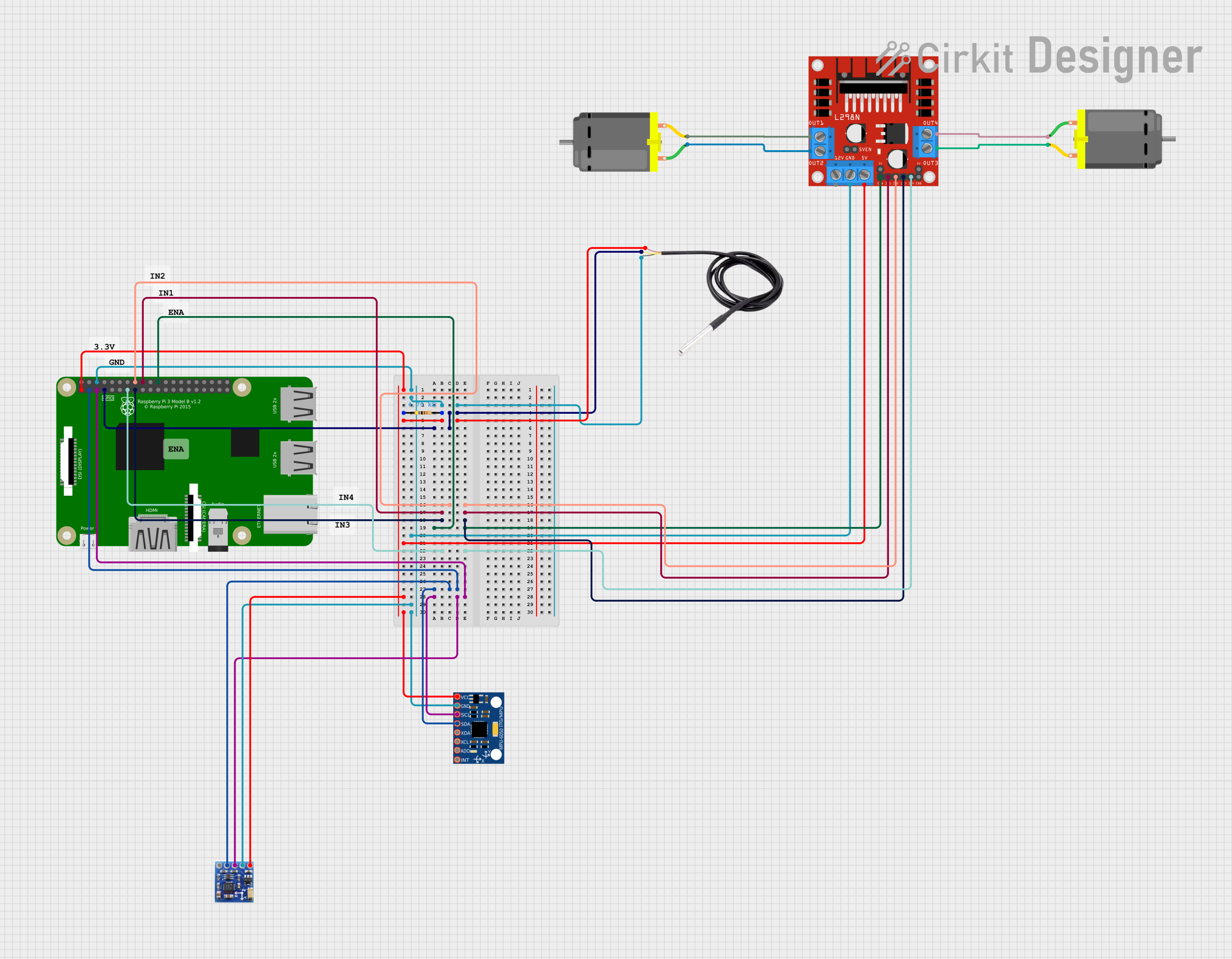 Open Project in Cirkit Designer
 Open Project in Cirkit Designer
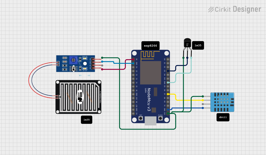 Open Project in Cirkit Designer
Explore Projects Built with Header 3
Open Project in Cirkit DesignerOpen Project in Cirkit DesignerOpen Project in Cirkit DesignerOpen Project in Cirkit DesignerCommon Applications and Use Cases
- Connecting sensors, modules, or peripherals to microcontrollers
- Power distribution in small circuits
- Prototyping and breadboard connections
- Modular PCB designs for easy assembly and disassembly
- Interfacing with Arduino, Raspberry Pi, and other development boards
Technical Specifications
Key Technical Details
- Number of Pins: 3
- Pin Spacing (Pitch): 2.54 mm (standard)
- Current Rating: Typically up to 3A per pin (varies by manufacturer)
- Voltage Rating: Typically up to 250V (varies by manufacturer)
- Material:
- Pins: Tin-plated or gold-plated copper
- Housing: Plastic (e.g., nylon or polyamide)
- Operating Temperature: -40°C to +105°C (varies by manufacturer)
- Mounting Type: Through-hole or surface-mount
Pin Configuration and Descriptions
The Header 3 connector consists of three pins, which can be configured for various purposes depending on the circuit design. Below is a general description of the pin layout:
| Pin Number | Description | Common Use |
|---|---|---|
| 1 | Signal or Power Input | Data signal or positive voltage |
| 2 | Ground (GND) | Circuit ground |
| 3 | Signal or Power Output | Data signal or negative voltage |
Note: The specific pin configuration may vary depending on the application. Always refer to the circuit schematic for proper usage.
Usage Instructions
How to Use the Header 3 in a Circuit
- Identify the Pinout: Determine the function of each pin (e.g., signal, power, ground) based on your circuit design.
- Soldering: If using a through-hole Header 3, solder the pins to the PCB. For breadboard use, simply insert the pins into the breadboard.
- Connect Wires or Cables: Use jumper wires or connectors to attach the Header 3 to other components or modules.
- Verify Connections: Double-check the connections to ensure proper alignment and avoid short circuits.
Important Considerations and Best Practices
- Pin Alignment: Ensure the pins are aligned correctly with the corresponding connections in your circuit.
- Current and Voltage Ratings: Do not exceed the specified current and voltage ratings to avoid damage.
- Secure Connections: Use locking connectors or heat-shrink tubing for added stability in high-vibration environments.
- Avoid Shorts: Ensure there is no accidental contact between adjacent pins, especially in high-power applications.
Example: Connecting a Header 3 to an Arduino UNO
Below is an example of how to use a Header 3 to connect an LED to an Arduino UNO:
Circuit Description
- Pin 1: Connected to Arduino digital pin 9 (signal for LED control)
- Pin 2: Connected to GND on the Arduino
- Pin 3: Connected to the positive terminal of the LED (via a resistor)
Arduino Code
// Example code to blink an LED connected via a Header 3 connector
// Pin 9 is used as the output pin for the LED signal

const int ledPin = 9; // Define the pin connected to the LED

void setup() {
  pinMode(ledPin, OUTPUT); // Set the LED pin as an output
}

void loop() {
  digitalWrite(ledPin, HIGH); // Turn the LED on
  delay(1000);               // Wait for 1 second
  digitalWrite(ledPin, LOW);  // Turn the LED off
  delay(1000);               // Wait for 1 second
}
Note: Always use a current-limiting resistor in series with the LED to prevent damage.
Troubleshooting and FAQs
Common Issues and Solutions
Loose Connections:
- Issue: The Header 3 pins are not making proper contact.
- Solution: Ensure the pins are securely soldered or inserted into the breadboard. Use locking connectors if necessary.
Short Circuits:
- Issue: Adjacent pins are accidentally shorted.
- Solution: Inspect the connections and ensure there is no exposed wire or solder bridging the pins.
Overheating:
- Issue: The connector becomes hot during operation.
- Solution: Check that the current and voltage do not exceed the rated limits of the Header 3.
Incorrect Pinout:
- Issue: The pins are connected incorrectly.
- Solution: Refer to the circuit schematic and verify the pin configuration.
FAQs
Q: Can I use a Header 3 for high-frequency signals?
- A: Yes, but ensure the connector and PCB layout are designed to minimize signal degradation.
Q: Are Header 3 connectors reusable?
- A: Yes, they can be reused, but repeated soldering and desoldering may degrade the pins.
Q: Can I use a Header 3 for power connections?
- A: Yes, as long as the current and voltage do not exceed the rated limits.
By following this documentation, you can effectively use a Header 3 connector in your electronic projects.