
How to Use TJA1040: Examples, Pinouts, and Specs
 Design with TJA1040 in Cirkit Designer
Introduction
The TJA1040 is a high-speed CAN (Controller Area Network) transceiver manufactured by NXP Semiconductors. It is designed to facilitate reliable communication between microcontrollers and CAN networks, making it an essential component in automotive and industrial applications. The TJA1040 offers low power consumption, high noise immunity, and supports data rates of up to 1 Mbps, ensuring robust and efficient data transmission in demanding environments.
Explore Projects Built with TJA1040
 Open Project in Cirkit Designer
 Open Project in Cirkit Designer
 Open Project in Cirkit Designer
 Open Project in Cirkit Designer
Explore Projects Built with TJA1040
Open Project in Cirkit DesignerOpen Project in Cirkit DesignerOpen Project in Cirkit DesignerOpen Project in Cirkit DesignerCommon Applications and Use Cases
- Automotive systems (e.g., engine control units, body control modules)
- Industrial automation and control
- Medical equipment
- Robotics and embedded systems
- Any application requiring high-speed CAN communication
Technical Specifications
Key Technical Details
| Parameter | Value |
|---|---|
| Supply Voltage (Vcc) | 4.5 V to 5.5 V |
| Data Rate | Up to 1 Mbps |
| Bus Voltage Range | -27 V to +40 V |
| Standby Current | < 10 µA |
| Operating Temperature | -40°C to +125°C |
| ESD Protection | ±6 kV (Human Body Model) |
| CAN Protocol Compatibility | ISO 11898-2 |
Pin Configuration and Descriptions
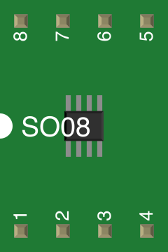
The TJA1040 is typically available in an 8-pin SO (Small Outline) package. Below is the pinout and description:
| Pin No. | Pin Name | Description |
|---|---|---|
| 1 | TXD | Transmit Data Input: Controls the state of the CAN bus. |
| 2 | GND | Ground: Connect to system ground. |
| 3 | Vcc | Supply Voltage: Connect to a 5 V power supply. |
| 4 | RXD | Receive Data Output: Outputs the state of the CAN bus. |
| 5 | Vref | Reference Voltage Output: Provides a reference voltage for external use. |
| 6 | CANL | CAN Low: Connect to the CAN bus low line. |
| 7 | CANH | CAN High: Connect to the CAN bus high line. |
| 8 | STB | Standby Control Input: Enables low-power standby mode when set high. |
Usage Instructions
How to Use the TJA1040 in a Circuit
- Power Supply: Connect the Vcc pin to a regulated 5 V power supply and the GND pin to the system ground.
- CAN Bus Connection: Connect the CANH and CANL pins to the respective high and low lines of the CAN bus.
- Microcontroller Interface:
- Connect the TXD pin to the microcontroller's CAN transmit pin.
- Connect the RXD pin to the microcontroller's CAN receive pin.
- Standby Mode: Use the STB pin to enable or disable standby mode. Pull the STB pin high to enter standby mode or low for normal operation.
- Termination Resistor: Ensure a 120-ohm termination resistor is placed across the CANH and CANL lines at each end of the bus for proper signal integrity.
Important Considerations and Best Practices
- ESD Protection: The TJA1040 includes built-in ESD protection, but additional external protection may be required in harsh environments.
- Power Supply Decoupling: Place a 100 nF ceramic capacitor close to the Vcc pin to filter noise and stabilize the power supply.
- Signal Integrity: Keep the CANH and CANL lines as short as possible and use twisted-pair cables to minimize electromagnetic interference (EMI).
- Standby Mode: Use standby mode to reduce power consumption when the transceiver is not actively communicating.
Example Code for Arduino UNO
Below is an example of how to interface the TJA1040 with an Arduino UNO using the MCP2515 CAN controller library:
#include <SPI.h>
#include <mcp_can.h>

// Define the SPI CS pin for the MCP2515 CAN controller
#define CAN_CS_PIN 10

// Initialize the MCP2515 CAN controller
MCP_CAN CAN(CAN_CS_PIN);

void setup() {
  Serial.begin(115200);
  while (!Serial);

  // Initialize the CAN bus at 500 kbps
  if (CAN.begin(MCP_ANY, CAN_500KBPS, MCP_8MHZ) == CAN_OK) {
    Serial.println("CAN bus initialized successfully!");
  } else {
    Serial.println("CAN bus initialization failed!");
    while (1);
  }

  // Set the CAN controller to normal mode
  CAN.setMode(MCP_NORMAL);
  Serial.println("CAN controller set to normal mode.");
}

void loop() {
  // Example: Send a CAN message
  byte data[8] = {0x01, 0x02, 0x03, 0x04, 0x05, 0x06, 0x07, 0x08};
  if (CAN.sendMsgBuf(0x100, 0, 8, data) == CAN_OK) {
    Serial.println("Message sent successfully!");
  } else {
    Serial.println("Error sending message.");
  }

  delay(1000); // Wait 1 second before sending the next message
}
Troubleshooting and FAQs
Common Issues and Solutions
No Communication on the CAN Bus:
- Verify the connections between the TJA1040, microcontroller, and CAN bus.
- Ensure the termination resistors (120 ohms) are correctly placed at both ends of the CAN bus.
- Check the power supply voltage (Vcc) and ensure it is within the specified range (4.5 V to 5.5 V).
High Power Consumption:
- Ensure the STB pin is set high to enable standby mode when the transceiver is not in use.
Data Corruption or Noise:
- Use twisted-pair cables for the CANH and CANL lines to reduce EMI.
- Check for proper grounding and minimize ground loops in the circuit.
Overheating:
- Verify that the supply voltage and current do not exceed the specified limits.
- Ensure proper ventilation and avoid placing the TJA1040 near heat sources.
FAQs
Q1: Can the TJA1040 operate at 3.3 V?
A1: No, the TJA1040 requires a supply voltage between 4.5 V and 5.5 V. For 3.3 V systems, consider using a level shifter or a transceiver designed for 3.3 V operation.
Q2: What is the maximum cable length for the CAN bus?
A2: The maximum cable length depends on the data rate. For example, at 1 Mbps, the maximum length is approximately 40 meters. For lower data rates, longer cable lengths are possible.
Q3: Is the TJA1040 compatible with ISO 11898-2?
A3: Yes, the TJA1040 is fully compliant with the ISO 11898-2 standard for high-speed CAN communication.
Q4: Can I use the TJA1040 in non-automotive applications?
A4: Yes, the TJA1040 is suitable for any application requiring high-speed CAN communication, including industrial and embedded systems.