
How to Use OP37 - Low Noise, Precision, High Speed Op Amp: Examples, Pinouts, and Specs
 Design with OP37 - Low Noise, Precision, High Speed Op Amp in Cirkit Designer
Introduction
The OP37, manufactured by Analog Devices, is a high-performance operational amplifier designed for applications requiring low noise, precision, and high-speed signal amplification. With its superior characteristics, the OP37 is widely used in instrumentation, audio processing, medical devices, and other precision signal processing applications.
Explore Projects Built with OP37 - Low Noise, Precision, High Speed Op Amp
 Open Project in Cirkit Designer
 Open Project in Cirkit Designer
 Open Project in Cirkit Designer
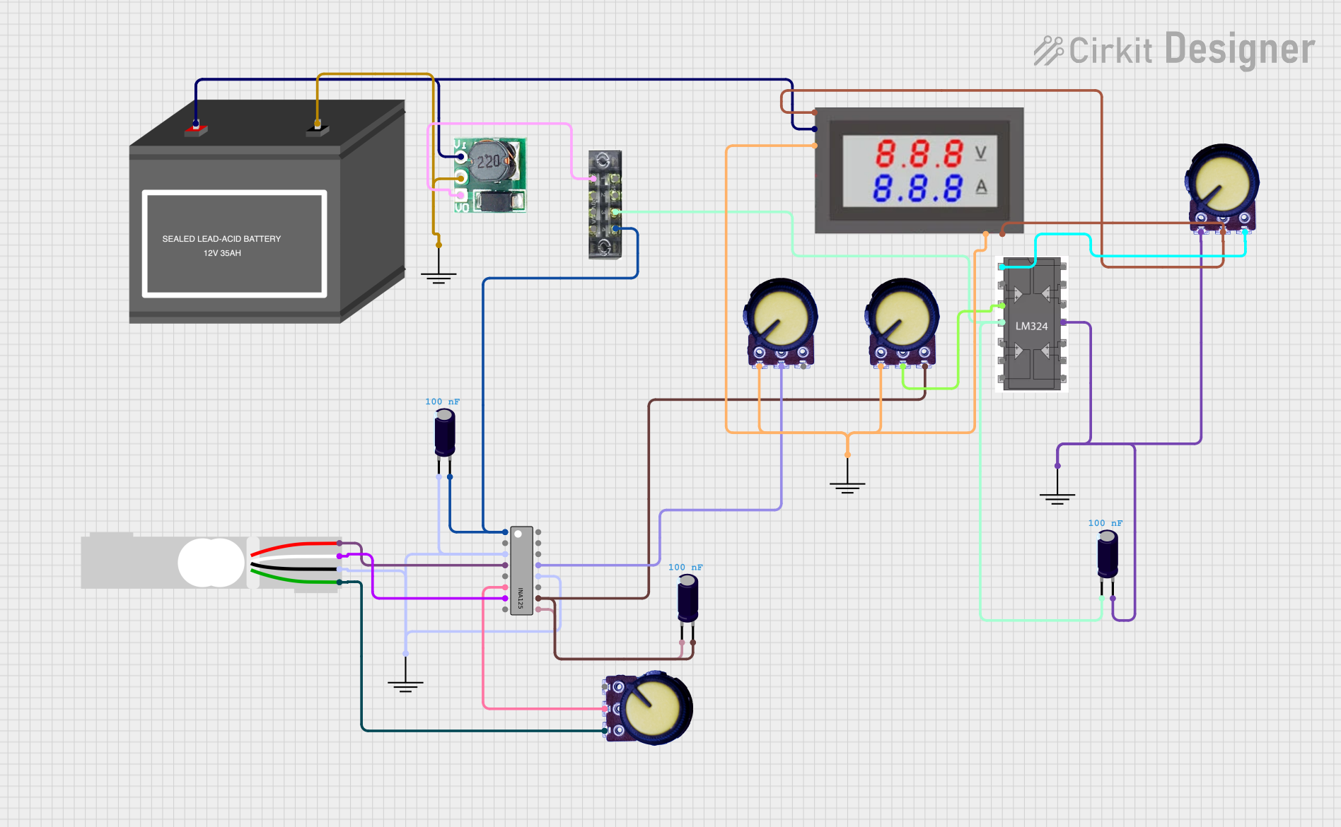 Open Project in Cirkit Designer
Explore Projects Built with OP37 - Low Noise, Precision, High Speed Op Amp
Open Project in Cirkit DesignerOpen Project in Cirkit DesignerOpen Project in Cirkit DesignerOpen Project in Cirkit DesignerCommon Applications
- High-precision instrumentation amplifiers
- Audio preamplifiers and equalizers
- Medical instrumentation (e.g., ECG, EEG amplifiers)
- Data acquisition systems
- Active filters and integrators
- High-speed signal processing circuits
Technical Specifications
Key Technical Details
| Parameter | Value |
|---|---|
| Supply Voltage Range | ±3 V to ±18 V |
| Input Offset Voltage | 25 µV (typical) |
| Input Bias Current | 10 nA (typical) |
| Input Noise Voltage | 3 nV/√Hz at 10 Hz |
| Gain Bandwidth Product | 63 MHz |
| Slew Rate | 17 V/µs |
| Output Voltage Swing | ±13 V (typical, with ±15 V supply) |
| Common-Mode Rejection Ratio | 120 dB (typical) |
| Power Supply Rejection Ratio | 120 dB (typical) |
| Operating Temperature Range | -25°C to +85°C |
| Package Options | 8-Pin PDIP, SOIC |
Pin Configuration and Descriptions
The OP37 is available in an 8-pin package. The pinout and descriptions are as follows:
| Pin Number | Pin Name | Description |
|---|---|---|
| 1 | Offset Null 1 | Offset voltage adjustment (connect to a |
| potentiometer for fine-tuning) | ||
| 2 | Inverting Input | Inverting input terminal (-) |
| 3 | Non-Inverting | Non-inverting input terminal (+) |
| Input | ||
| 4 | V- (Negative | Negative power supply terminal |
| Supply) | ||
| 5 | Offset Null 2 | Offset voltage adjustment (connect to a |
| potentiometer for fine-tuning) | ||
| 6 | Output | Amplifier output terminal |
| 7 | V+ (Positive | Positive power supply terminal |
| Supply) | ||
| 8 | NC (No Connect) | Not connected internally |
Usage Instructions
How to Use the OP37 in a Circuit
- Power Supply: Connect the OP37 to a dual power supply (e.g., ±15 V) for optimal performance. Ensure the supply voltage does not exceed the specified range (±18 V maximum).
- Input Connections:
- Connect the signal source to the non-inverting input (Pin 3) or the inverting input (Pin 2), depending on the desired configuration (non-inverting or inverting amplifier).
- Use appropriate resistors to set the gain of the amplifier.
- Offset Adjustment: If precise offset voltage adjustment is required, connect a 10 kΩ potentiometer between Offset Null 1 (Pin 1) and Offset Null 2 (Pin 5), with the wiper connected to the negative supply (Pin 4).
- Output Load: Ensure the load connected to the output (Pin 6) does not exceed the amplifier's drive capability. For best performance, use a load impedance of at least 2 kΩ.
- Bypass Capacitors: Place decoupling capacitors (e.g., 0.1 µF ceramic and 10 µF electrolytic) close to the power supply pins (Pins 4 and 7) to minimize noise and ensure stability.
Important Considerations and Best Practices
- Avoid exceeding the input voltage range to prevent damage or distortion.
- Use proper grounding techniques to minimize noise and interference.
- For high-frequency applications, consider adding a small capacitor (e.g., 10 pF) across the feedback resistor to improve stability.
- Ensure the layout of the PCB minimizes parasitic capacitance and inductance, especially in high-speed applications.
Example: Using the OP37 with an Arduino UNO
The OP37 can be used to amplify analog signals for an Arduino UNO. Below is an example of a non-inverting amplifier circuit with a gain of 10.
Circuit Setup
- Connect the OP37's V+ (Pin 7) to +12 V and V- (Pin 4) to -12 V.
- Connect the signal source to the non-inverting input (Pin 3).
- Use a resistor divider to set the gain: R1 = 1 kΩ (feedback resistor), R2 = 100 Ω (resistor to ground).
- Connect the output (Pin 6) to an analog input pin on the Arduino (e.g., A0).
Arduino Code
// Arduino code to read amplified signal from OP37 and display it
// on the serial monitor.

const int analogPin = A0; // Analog pin connected to OP37 output
int sensorValue = 0;      // Variable to store the analog reading

void setup() {
  Serial.begin(9600); // Initialize serial communication at 9600 baud
}

void loop() {
  sensorValue = analogRead(analogPin); // Read the analog value
  float voltage = sensorValue * (5.0 / 1023.0); // Convert to voltage
  Serial.print("Amplified Voltage: ");
  Serial.print(voltage);
  Serial.println(" V");
  delay(500); // Wait for 500 ms before the next reading
}
Troubleshooting and FAQs
Common Issues and Solutions
No Output Signal:
- Verify the power supply connections and ensure the voltage is within the specified range.
- Check the input signal and ensure it is within the input voltage range of the OP37.
- Confirm that the feedback network is correctly connected.
Output Distortion:
- Ensure the load impedance is not too low (minimum 2 kΩ recommended).
- Check for excessive input signal levels that may cause clipping.
High Noise Levels:
- Use proper grounding and shielding techniques to minimize interference.
- Add bypass capacitors close to the power supply pins.
Instability or Oscillation:
- Add a small capacitor (e.g., 10 pF) across the feedback resistor to improve stability.
- Ensure the PCB layout minimizes parasitic capacitance and inductance.
FAQs
Q: Can the OP37 operate with a single power supply?
A: Yes, the OP37 can operate with a single supply, but the input and output signals must remain within the specified voltage range. A virtual ground may be required for proper operation.
Q: What is the maximum gain I can achieve with the OP37?
A: The OP37 is optimized for gains of 5 or higher. For lower gains, consider using a different operational amplifier.
Q: How do I minimize offset voltage in my circuit?
A: Use the offset null pins (Pins 1 and 5) with a potentiometer to fine-tune the offset voltage.