Cirkit Designer Logo
Cirkit Designer
Your all-in-one circuit design IDE
Home / 
Component Documentation

How to Use 18650 li-ion Battery Charger Module DC-DC Step Up Booster Converter: Examples, Pinouts, and Specs

Image of 18650 li-ion Battery Charger Module DC-DC Step Up Booster Converter
Cirkit Designer LogoDesign with 18650 li-ion Battery Charger Module DC-DC Step Up Booster Converter in Cirkit Designer

Introduction

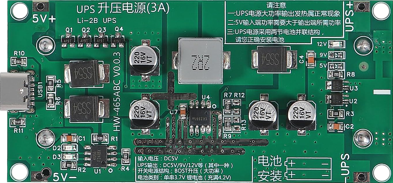
The 18650 Li-ion Battery Charger Module DC-DC Step Up Booster Converter (Manufacturer: DWEII, Part ID: 119cad72-687d-42fa-b602-45b34ad48c44) is a versatile electronic module designed for charging 18650 lithium-ion batteries and providing a regulated DC output. This module combines a charging circuit with a DC-DC step-up converter, making it ideal for portable power applications.

Explore Projects Built with 18650 li-ion Battery Charger Module DC-DC Step Up Booster Converter

Use Cirkit Designer to design, explore, and prototype these projects online. Some projects support real-time simulation. Click "Open Project" to start designing instantly!
Battery-Powered 18650 Li-ion Charger with USB Output and Adjustable Voltage Regulator
Image of Breadboard: A project utilizing 18650 li-ion Battery Charger Module DC-DC Step Up Booster Converter in a practical application
This circuit is a battery management and power supply system that uses three 3.7V batteries connected to a 3S 10A Li-ion 18650 Charger Protection Board Module for balanced charging and protection. The system includes a TP4056 Battery Charging Protection Module for additional charging safety, a Step Up Boost Power Converter to regulate and boost the voltage, and a USB regulator to provide a stable 5V output, controlled by a push switch.
Cirkit Designer LogoOpen Project in Cirkit Designer
Battery-Powered Lora G2 Node Station with 18650 Li-ion Batteries and Boost Converter
Image of Custom-Lora-G2-Node: A project utilizing 18650 li-ion Battery Charger Module DC-DC Step Up Booster Converter in a practical application
This circuit is a portable power supply system that uses multiple 18650 Li-ion batteries to provide a stable 5V output through a boost converter. It includes a fast charging module with a USB-C input for recharging the batteries and a battery indicator for monitoring the battery status. The system powers a Lora G2 Node Station, making it suitable for wireless communication applications.
Cirkit Designer LogoOpen Project in Cirkit Designer
Battery-Powered Audio Playback and Amplification System
Image of recorder: A project utilizing 18650 li-ion Battery Charger Module DC-DC Step Up Booster Converter in a practical application
This circuit is designed to charge 18650 lithium-ion batteries using a TP4056 charger module, and then boost the voltage using an XL 6009 Boost Module. The boosted voltage is regulated by a 7805 voltage regulator to provide a stable 5V output, which powers an ISD1820 voice recording and playback module. The audio signal from the ISD1820 is then amplified by an LM386 audio amplifier module and output through a loudspeaker.
Cirkit Designer LogoOpen Project in Cirkit Designer
Battery-Powered Adjustable Voltage Regulator with Li-ion 18650 Batteries and BMS
Image of mini ups: A project utilizing 18650 li-ion Battery Charger Module DC-DC Step Up Booster Converter in a practical application
This circuit is a power management system that uses four Li-ion 18650 batteries connected to a 2S 30A BMS for battery management and protection. The system includes step-up and step-down voltage regulators to provide adjustable output voltages, controlled by a rocker switch, and multiple DC jacks for power input and output.
Cirkit Designer LogoOpen Project in Cirkit Designer

Explore Projects Built with 18650 li-ion Battery Charger Module DC-DC Step Up Booster Converter

Use Cirkit Designer to design, explore, and prototype these projects online. Some projects support real-time simulation. Click "Open Project" to start designing instantly!
Image of Breadboard: A project utilizing 18650 li-ion Battery Charger Module DC-DC Step Up Booster Converter in a practical application
Battery-Powered 18650 Li-ion Charger with USB Output and Adjustable Voltage Regulator
This circuit is a battery management and power supply system that uses three 3.7V batteries connected to a 3S 10A Li-ion 18650 Charger Protection Board Module for balanced charging and protection. The system includes a TP4056 Battery Charging Protection Module for additional charging safety, a Step Up Boost Power Converter to regulate and boost the voltage, and a USB regulator to provide a stable 5V output, controlled by a push switch.
Cirkit Designer LogoOpen Project in Cirkit Designer
Image of Custom-Lora-G2-Node: A project utilizing 18650 li-ion Battery Charger Module DC-DC Step Up Booster Converter in a practical application
Battery-Powered Lora G2 Node Station with 18650 Li-ion Batteries and Boost Converter
This circuit is a portable power supply system that uses multiple 18650 Li-ion batteries to provide a stable 5V output through a boost converter. It includes a fast charging module with a USB-C input for recharging the batteries and a battery indicator for monitoring the battery status. The system powers a Lora G2 Node Station, making it suitable for wireless communication applications.
Cirkit Designer LogoOpen Project in Cirkit Designer
Image of recorder: A project utilizing 18650 li-ion Battery Charger Module DC-DC Step Up Booster Converter in a practical application
Battery-Powered Audio Playback and Amplification System
This circuit is designed to charge 18650 lithium-ion batteries using a TP4056 charger module, and then boost the voltage using an XL 6009 Boost Module. The boosted voltage is regulated by a 7805 voltage regulator to provide a stable 5V output, which powers an ISD1820 voice recording and playback module. The audio signal from the ISD1820 is then amplified by an LM386 audio amplifier module and output through a loudspeaker.
Cirkit Designer LogoOpen Project in Cirkit Designer
Image of mini ups: A project utilizing 18650 li-ion Battery Charger Module DC-DC Step Up Booster Converter in a practical application
Battery-Powered Adjustable Voltage Regulator with Li-ion 18650 Batteries and BMS
This circuit is a power management system that uses four Li-ion 18650 batteries connected to a 2S 30A BMS for battery management and protection. The system includes step-up and step-down voltage regulators to provide adjustable output voltages, controlled by a rocker switch, and multiple DC jacks for power input and output.
Cirkit Designer LogoOpen Project in Cirkit Designer

Common Applications and Use Cases

  • Power banks and portable chargers
  • DIY electronics projects
  • Battery-powered devices
  • Emergency lighting systems
  • Robotics and IoT applications

Technical Specifications

Below are the key technical details of the module:

Parameter Specification
Input Voltage Range 5V DC (via micro-USB or solder pads)
Output Voltage Adjustable (default: 5V DC)
Output Current Up to 2A (depending on load and battery)
Charging Current 1A (default, adjustable via resistor)
Battery Type Supported 18650 Li-ion
Protection Features Overcharge, over-discharge, short circuit
Dimensions 36mm x 17mm x 6mm

Pin Configuration and Descriptions

The module has the following key connections:

Pin/Port Description
Micro-USB Input Connects to a 5V DC power source for charging the battery.
BAT+ Positive terminal for the 18650 battery.
BAT- Negative terminal for the 18650 battery.
OUT+ Positive terminal for the output voltage.
OUT- Negative terminal for the output voltage.
Adjustment Potentiometer Used to adjust the output voltage (default is set to 5V).

Usage Instructions

How to Use the Module in a Circuit

  1. Connect the Battery:

    • Solder the 18650 battery's positive terminal to the BAT+ pin and the negative terminal to the BAT- pin.
    • Ensure the battery is not over-discharged before connecting.
  2. Power the Module:

    • Use a micro-USB cable to connect the module to a 5V DC power source (e.g., USB charger or power adapter).
    • Alternatively, solder a 5V DC input to the designated solder pads.
  3. Adjust the Output Voltage:

    • Use the onboard potentiometer to adjust the output voltage as needed. Turn clockwise to increase the voltage and counterclockwise to decrease it.
  4. Connect the Load:

    • Attach the load to the OUT+ and OUT- terminals. Ensure the load does not exceed the module's maximum output current (2A).

Important Considerations and Best Practices

  • Battery Protection: Ensure the 18650 battery has built-in protection circuitry or use a protected battery to prevent over-discharge or overcurrent.
  • Heat Dissipation: Avoid operating the module at maximum current for extended periods without proper ventilation or heat sinking.
  • Voltage Adjustment: Use a multimeter to verify the output voltage after adjustment to avoid damaging connected devices.
  • Polarity: Double-check all connections to ensure correct polarity. Reversing the battery or load connections can damage the module.

Example: Using with Arduino UNO

The module can be used to power an Arduino UNO. Below is an example of how to connect and use it:

  1. Connect the OUT+ and OUT- terminals of the module to the Arduino's VIN and GND pins, respectively.
  2. Ensure the output voltage is set to 7-12V (recommended input range for Arduino UNO).

Here is a simple Arduino sketch to test the setup:

// Simple LED Blink Test for Arduino UNO
// Ensure the 18650 charger module is providing 7-12V to the Arduino's VIN pin.

void setup() {
  pinMode(13, OUTPUT); // Set pin 13 (built-in LED) as an output
}

void loop() {
  digitalWrite(13, HIGH); // Turn the LED on
  delay(1000);            // Wait for 1 second
  digitalWrite(13, LOW);  // Turn the LED off
  delay(1000);            // Wait for 1 second
}

Troubleshooting and FAQs

Common Issues and Solutions

  1. Module Not Charging the Battery:

    • Cause: Insufficient input voltage or current.
    • Solution: Ensure the input power source provides a stable 5V and at least 1A.
  2. Output Voltage Not Adjustable:

    • Cause: Faulty potentiometer or incorrect adjustment.
    • Solution: Verify the potentiometer is functional and adjust it carefully while monitoring the output voltage with a multimeter.
  3. Overheating:

    • Cause: Excessive load or poor ventilation.
    • Solution: Reduce the load current or improve heat dissipation by adding a heatsink or ensuring proper airflow.
  4. No Output Voltage:

    • Cause: Battery not connected or discharged below the cutoff voltage.
    • Solution: Check the battery connection and charge the battery if necessary.

FAQs

Q1: Can I use this module with batteries other than 18650 Li-ion?
A1: This module is specifically designed for 18650 Li-ion batteries. Using other battery types may result in improper charging or damage.

Q2: What is the default output voltage of the module?
A2: The default output voltage is set to 5V, but it can be adjusted using the onboard potentiometer.

Q3: Can I charge multiple 18650 batteries in parallel?
A3: Yes, but ensure the batteries are of the same type, capacity, and charge level. Also, verify that the total charging current does not exceed the module's limit.

Q4: Is the module safe to use without additional protection circuits?
A4: The module includes basic protection features, but it is recommended to use protected 18650 batteries for added safety.

This concludes the documentation for the 18650 Li-ion Battery Charger Module DC-DC Step Up Booster Converter.