Cirkit Designer Logo
Cirkit Designer
Your all-in-one circuit design IDE
Home / 
Component Documentation

How to Use HG7881 H-Bridge 4CH DC - 2CH Stepper Motor Driver Board: Examples, Pinouts, and Specs

Image of HG7881 H-Bridge 4CH DC - 2CH Stepper Motor Driver Board
Cirkit Designer LogoDesign with HG7881 H-Bridge 4CH DC - 2CH Stepper Motor Driver Board in Cirkit Designer

Introduction

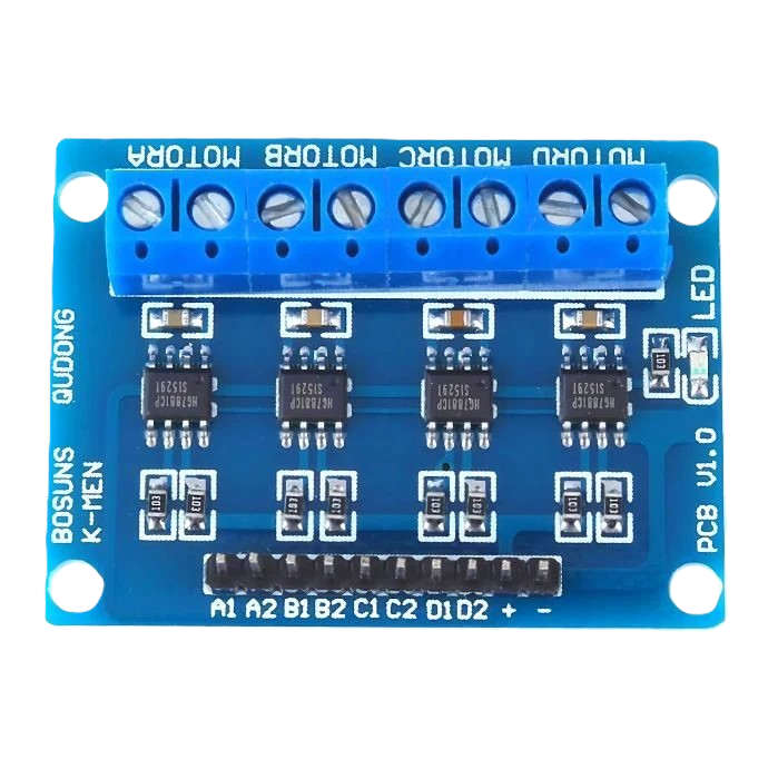
The HG7881 H-Bridge 4CH DC - 2CH Stepper Motor Driver Board, manufactured by Adafruit (Part ID: HG7881 H-Bridge 4CH DC - 2CH Stepper Motor Driver Board), is a compact and efficient motor driver board. It is designed to control up to four DC motors or two stepper motors, providing bidirectional control and speed regulation. The board is based on the HG7881 H-Bridge IC, which ensures reliable and efficient motor operation.

This motor driver board is ideal for robotics, automation, and other projects requiring precise motor control. Its small size and ease of use make it a popular choice for hobbyists and professionals alike.

Explore Projects Built with HG7881 H-Bridge 4CH DC - 2CH Stepper Motor Driver Board

Use Cirkit Designer to design, explore, and prototype these projects online. Some projects support real-time simulation. Click "Open Project" to start designing instantly!
Stepper Motor Control System with TB6600 Driver and DKC-1A Controller
Image of Copy of Copy of PLC-Based Step Motor Speed and Direction Control System: A project utilizing HG7881 H-Bridge 4CH DC - 2CH Stepper Motor Driver Board in a practical application
This circuit controls a bipolar stepper motor using a tb6600 micro stepping motor driver and a DKC-1A stepper motor controller. The system is powered by a 24VDC power supply and includes a relay module for additional control functionalities.
Cirkit Designer LogoOpen Project in Cirkit Designer
Stepper Motor Control System with TB6600 Driver and Relay Integration
Image of Copy of Copy of Copy of PLC-Based Step Motor Speed and Direction Control System: A project utilizing HG7881 H-Bridge 4CH DC - 2CH Stepper Motor Driver Board in a practical application
This circuit controls a bipolar stepper motor using a tb6600 micro stepping motor driver and a DKC-1A stepper motor controller. It includes a 24VDC power supply, a 4-channel relay module, and panel mount banana sockets for power connections. The motor driver and controller are interconnected to manage the motor's direction and pulse signals.
Cirkit Designer LogoOpen Project in Cirkit Designer
CNC Machine Control System with Dual tb6600 Stepper Drivers and MAch3 USB Interface
Image of Jayshree CNC: A project utilizing HG7881 H-Bridge 4CH DC - 2CH Stepper Motor Driver Board in a practical application
This circuit appears to be a control system for a CNC machine or similar automated equipment. It includes two tb6600 Micro Stepping Motor Drivers for controlling stepper motors, a DC power source with a step-down buck converter to provide the necessary voltage levels, and a 4-channel relay module for switching higher power loads. The MAch3 CNC USB interface suggests the system is designed to interface with computer numerical control software, and the RMCS_3001 BLDC Driver indicates the presence of a brushless DC motor control. The Tiva C launchpad microcontroller and various connectors imply that the system is modular and may be programmable for specific automation tasks.
Cirkit Designer LogoOpen Project in Cirkit Designer
Arduino Mega 2560-Controlled Stepper Motors with RFID Access and Traffic Light Indication
Image of Copy of test: A project utilizing HG7881 H-Bridge 4CH DC - 2CH Stepper Motor Driver Board in a practical application
This circuit controls two 28BYJ-48 stepper motors using A4988 stepper motor driver carriers, interfaced with an Arduino Mega 2560 microcontroller. It features an RFID-RC522 module for RFID reading, a 16x4 LCD display with I2C interface for user interaction, and a piezo speaker for audio feedback. Additionally, there is a traffic light module controlled by the Arduino, and a 48V to 5V converter to step down voltage for the logic levels. The power supply provides 12V to the motor drivers and is connected to a standard power outlet.
Cirkit Designer LogoOpen Project in Cirkit Designer

Explore Projects Built with HG7881 H-Bridge 4CH DC - 2CH Stepper Motor Driver Board

Use Cirkit Designer to design, explore, and prototype these projects online. Some projects support real-time simulation. Click "Open Project" to start designing instantly!
Image of Copy of Copy of PLC-Based Step Motor Speed and Direction Control System: A project utilizing HG7881 H-Bridge 4CH DC - 2CH Stepper Motor Driver Board in a practical application
Stepper Motor Control System with TB6600 Driver and DKC-1A Controller
This circuit controls a bipolar stepper motor using a tb6600 micro stepping motor driver and a DKC-1A stepper motor controller. The system is powered by a 24VDC power supply and includes a relay module for additional control functionalities.
Cirkit Designer LogoOpen Project in Cirkit Designer
Image of Copy of Copy of Copy of PLC-Based Step Motor Speed and Direction Control System: A project utilizing HG7881 H-Bridge 4CH DC - 2CH Stepper Motor Driver Board in a practical application
Stepper Motor Control System with TB6600 Driver and Relay Integration
This circuit controls a bipolar stepper motor using a tb6600 micro stepping motor driver and a DKC-1A stepper motor controller. It includes a 24VDC power supply, a 4-channel relay module, and panel mount banana sockets for power connections. The motor driver and controller are interconnected to manage the motor's direction and pulse signals.
Cirkit Designer LogoOpen Project in Cirkit Designer
Image of Jayshree CNC: A project utilizing HG7881 H-Bridge 4CH DC - 2CH Stepper Motor Driver Board in a practical application
CNC Machine Control System with Dual tb6600 Stepper Drivers and MAch3 USB Interface
This circuit appears to be a control system for a CNC machine or similar automated equipment. It includes two tb6600 Micro Stepping Motor Drivers for controlling stepper motors, a DC power source with a step-down buck converter to provide the necessary voltage levels, and a 4-channel relay module for switching higher power loads. The MAch3 CNC USB interface suggests the system is designed to interface with computer numerical control software, and the RMCS_3001 BLDC Driver indicates the presence of a brushless DC motor control. The Tiva C launchpad microcontroller and various connectors imply that the system is modular and may be programmable for specific automation tasks.
Cirkit Designer LogoOpen Project in Cirkit Designer
Image of Copy of test: A project utilizing HG7881 H-Bridge 4CH DC - 2CH Stepper Motor Driver Board in a practical application
Arduino Mega 2560-Controlled Stepper Motors with RFID Access and Traffic Light Indication
This circuit controls two 28BYJ-48 stepper motors using A4988 stepper motor driver carriers, interfaced with an Arduino Mega 2560 microcontroller. It features an RFID-RC522 module for RFID reading, a 16x4 LCD display with I2C interface for user interaction, and a piezo speaker for audio feedback. Additionally, there is a traffic light module controlled by the Arduino, and a 48V to 5V converter to step down voltage for the logic levels. The power supply provides 12V to the motor drivers and is connected to a standard power outlet.
Cirkit Designer LogoOpen Project in Cirkit Designer

Common Applications

  • Robotics and automation systems
  • Remote-controlled vehicles
  • Conveyor belts and motorized platforms
  • DIY projects involving DC or stepper motors
  • Educational projects for learning motor control

Technical Specifications

Key Technical Details

  • Input Voltage (VCC): 2.5V to 12V DC
  • Output Current (per channel): 800mA (maximum)
  • Control Logic Voltage: 2.5V to 6V
  • Number of Channels: 4 (for DC motors) or 2 (for stepper motors)
  • Motor Type Support: DC motors and stepper motors
  • Dimensions: 29mm x 23mm x 8mm
  • Weight: ~5g
  • Operating Temperature Range: -20°C to 85°C

Pin Configuration and Descriptions

The HG7881 motor driver board has the following pin layout:

Input Pins (Control Logic)

Pin Name Description
IN1 Control input for Motor A (Channel 1)
IN2 Control input for Motor A (Channel 2)
IN3 Control input for Motor B (Channel 3)
IN4 Control input for Motor B (Channel 4)

Output Pins (Motor Connections)

Pin Name Description
OUT1 Output for Motor A (Channel 1)
OUT2 Output for Motor A (Channel 2)
OUT3 Output for Motor B (Channel 3)
OUT4 Output for Motor B (Channel 4)

Power and Ground Pins

Pin Name Description
VCC Power supply input (2.5V to 12V DC)
GND Ground connection

Usage Instructions

How to Use the Component in a Circuit

  1. Power the Board:

    • Connect the VCC pin to a DC power source (2.5V to 12V).
    • Connect the GND pin to the ground of your power source.
  2. Connect Motors:

    • For DC motors, connect the motor terminals to the corresponding output pins (e.g., OUT1 and OUT2 for Motor A).
    • For stepper motors, connect the motor coils to the output pins (e.g., OUT1, OUT2, OUT3, and OUT4).
  3. Control Logic:

    • Use a microcontroller (e.g., Arduino UNO) to send control signals to the input pins (IN1, IN2, IN3, IN4).
    • Set the input pins HIGH or LOW to control the direction and speed of the motors.
  4. Speed Control:

    • Use PWM (Pulse Width Modulation) signals on the input pins to regulate motor speed.

Important Considerations and Best Practices

  • Ensure the power supply voltage matches the motor's operating voltage.
  • Do not exceed the maximum current rating of 800mA per channel.
  • Use proper heat dissipation methods if operating at high currents for extended periods.
  • Double-check all connections before powering the board to avoid damage.

Example Code for Arduino UNO

The following example demonstrates how to control a DC motor connected to the HG7881 motor driver board using an Arduino UNO.

// Example: Controlling a DC motor with HG7881 and Arduino UNO

// Define control pins for Motor A
const int IN1 = 9; // Connect to IN1 on the motor driver
const int IN2 = 10; // Connect to IN2 on the motor driver

void setup() {
  // Set motor control pins as outputs
  pinMode(IN1, OUTPUT);
  pinMode(IN2, OUTPUT);
}

void loop() {
  // Rotate motor forward
  digitalWrite(IN1, HIGH); // Set IN1 HIGH
  digitalWrite(IN2, LOW);  // Set IN2 LOW
  delay(2000);             // Run motor for 2 seconds

  // Stop motor
  digitalWrite(IN1, LOW);  // Set IN1 LOW
  digitalWrite(IN2, LOW);  // Set IN2 LOW
  delay(1000);             // Wait for 1 second

  // Rotate motor backward
  digitalWrite(IN1, LOW);  // Set IN1 LOW
  digitalWrite(IN2, HIGH); // Set IN2 HIGH
  delay(2000);             // Run motor for 2 seconds

  // Stop motor
  digitalWrite(IN1, LOW);  // Set IN1 LOW
  digitalWrite(IN2, LOW);  // Set IN2 LOW
  delay(1000);             // Wait for 1 second
}

Troubleshooting and FAQs

Common Issues and Solutions

  1. Motor Not Spinning:

    • Cause: Incorrect wiring or loose connections.
    • Solution: Double-check all connections, ensuring the motor is properly connected to the output pins and the control signals are correctly applied.
  2. Motor Spins in the Wrong Direction:

    • Cause: Control signals are reversed.
    • Solution: Swap the HIGH and LOW signals on the input pins (e.g., IN1 and IN2).
  3. Motor Speed is Inconsistent:

    • Cause: Insufficient power supply or unstable PWM signals.
    • Solution: Use a stable power source and ensure the PWM signal is properly configured.
  4. Board Overheating:

    • Cause: Exceeding the maximum current rating.
    • Solution: Reduce the load on the motor or use a heat sink for better heat dissipation.

FAQs

  • Can I use this board to control a servo motor?

    • No, this board is designed for DC and stepper motors. Servo motors require a different control mechanism.
  • What happens if I exceed the voltage rating?

    • Exceeding the voltage rating can damage the board and connected components. Always stay within the specified voltage range.
  • Can I control multiple motors simultaneously?

    • Yes, you can control up to four DC motors or two stepper motors simultaneously using this board.
  • Is this board compatible with Raspberry Pi?

    • Yes, the board can be controlled by a Raspberry Pi, but you may need level shifters if the control logic voltage differs.

This concludes the documentation for the HG7881 H-Bridge 4CH DC - 2CH Stepper Motor Driver Board.