
How to Use 12V/24V 6-Way Blade Fuse Block with LED Indicator: Examples, Pinouts, and Specs
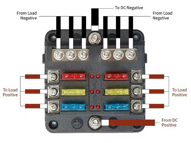
 Design with 12V/24V 6-Way Blade Fuse Block with LED Indicator in Cirkit Designer
Introduction
The 12V/24V 6-Way Blade Fuse Block with LED Indicator is a compact and efficient solution for managing multiple electrical circuits in automotive, marine, and industrial applications. This fuse block is designed to accommodate up to six standard blade fuses, providing overcurrent protection for individual circuits. The built-in LED indicators simplify troubleshooting by illuminating when a fuse is blown, allowing for quick identification and replacement.
Explore Projects Built with 12V/24V 6-Way Blade Fuse Block with LED Indicator
 Open Project in Cirkit Designer
 Open Project in Cirkit Designer
 Open Project in Cirkit Designer
 Open Project in Cirkit Designer
Explore Projects Built with 12V/24V 6-Way Blade Fuse Block with LED Indicator
Open Project in Cirkit DesignerOpen Project in Cirkit DesignerOpen Project in Cirkit DesignerOpen Project in Cirkit DesignerCommon Applications and Use Cases
- Automotive electrical systems (cars, trucks, RVs)
- Marine electrical systems (boats, yachts)
- Industrial equipment and machinery
- Solar power systems
- Custom electronics projects requiring circuit protection
Technical Specifications
Key Technical Details
| Parameter | Specification |
|---|---|
| Operating Voltage | 12V / 24V DC |
| Maximum Current per Fuse | 30A |
| Total Current Capacity | 100A |
| Fuse Type | Standard blade fuses (ATO/ATC) |
| LED Indicator Voltage | 12V / 24V DC (matches system) |
| Material | Flame-retardant plastic housing |
| Mounting Options | Screw-mounted |
| Dimensions | Varies by model (e.g., 95x85x35mm) |
Pin Configuration and Descriptions
The fuse block features a simple layout for easy installation and wiring. Below is a description of the terminals and their functions:
| Terminal Name | Description |
|---|---|
| Positive Bus | Main positive input terminal for connecting the power source (12V/24V DC). |
| Negative Bus | Common ground terminal for connecting the negative side of the circuit. |
| Fuse Slots | Six slots for standard blade fuses, each protecting an individual circuit. |
| Output Terminals | Six output terminals corresponding to each fuse slot. |
| LED Indicators | One LED per fuse slot, lights up when the corresponding fuse is blown. |
Usage Instructions
How to Use the Component in a Circuit
- Mount the Fuse Block: Secure the fuse block to a flat surface using screws or other mounting hardware.
- Connect the Power Source:
- Attach the positive wire from the 12V/24V DC power source to the
Positive Busterminal. - Connect the negative wire to the
Negative Busterminal.
- Attach the positive wire from the 12V/24V DC power source to the
- Install Fuses:
- Insert standard blade fuses (ATO/ATC type) into the fuse slots. Ensure the fuse ratings match the current requirements of your circuits.
- Connect Circuits:
- Attach the positive wires of your circuits to the corresponding
Output Terminals. - Connect the negative wires of your circuits to the
Negative Busterminal.
- Attach the positive wires of your circuits to the corresponding
- Power On:
- Turn on the power source and verify that all circuits are functioning correctly.
- If a fuse blows, the corresponding LED indicator will light up, signaling the need for replacement.
Important Considerations and Best Practices
- Fuse Ratings: Always use fuses with appropriate current ratings for your circuits to prevent damage to connected devices.
- Wire Gauge: Use wires with sufficient gauge to handle the current load of each circuit.
- Secure Connections: Ensure all terminals are tightly secured to prevent loose connections and potential electrical hazards.
- Environment: Install the fuse block in a dry, well-ventilated area to avoid exposure to moisture or extreme temperatures.
- LED Indicators: Verify that the LED indicators are functioning properly during installation.
Example: Connecting to an Arduino UNO
The fuse block can be used to protect circuits connected to an Arduino UNO. Below is an example of wiring and code to monitor a simple LED circuit:
Wiring
- Connect the
Positive Busterminal to a 12V DC power source. - Connect the
Negative Busterminal to the ground of the power source. - Insert a 1A blade fuse into one of the fuse slots.
- Connect the output terminal of the fuse slot to the positive lead of the LED (via a 220-ohm resistor).
- Connect the negative lead of the LED to the
Negative Bus.
Arduino Code
// Example code to blink an LED connected to a fuse-protected circuit
const int ledPin = 13; // Pin connected to the LED

void setup() {
  pinMode(ledPin, OUTPUT); // Set the LED pin as an output
}

void loop() {
  digitalWrite(ledPin, HIGH); // Turn the LED on
  delay(1000); // Wait for 1 second
  digitalWrite(ledPin, LOW); // Turn the LED off
  delay(1000); // Wait for 1 second
}
Troubleshooting and FAQs
Common Issues and Solutions
| Issue | Possible Cause | Solution |
|---|---|---|
| LED indicator does not light up when a fuse blows | Faulty LED or incorrect wiring | Check the wiring and replace the LED if necessary. |
| Fuse blows frequently | Overcurrent in the circuit | Verify the circuit's current draw and use a fuse with the correct rating. |
| No power to connected circuits | Loose connections or blown fuse | Inspect all connections and replace any blown fuses. |
| LED indicators light up incorrectly | Incorrect polarity or wiring error | Ensure proper polarity and verify all connections. |
FAQs
Can I use this fuse block for AC circuits?
- No, this fuse block is designed for DC circuits only (12V/24V).
What happens if I use a fuse with a higher rating than required?
- Using a higher-rated fuse may not protect your circuit effectively, potentially causing damage to connected devices.
Can I use fewer than six fuses?
- Yes, you can use as many fuse slots as needed. Unused slots can remain empty without affecting functionality.
Is the fuse block waterproof?
- Most models are not waterproof. If used in a marine or outdoor environment, ensure it is installed in a protected location or use a waterproof enclosure.