How to Use Power Module GM V1.0: Examples, Pinouts, and Specs
Introduction
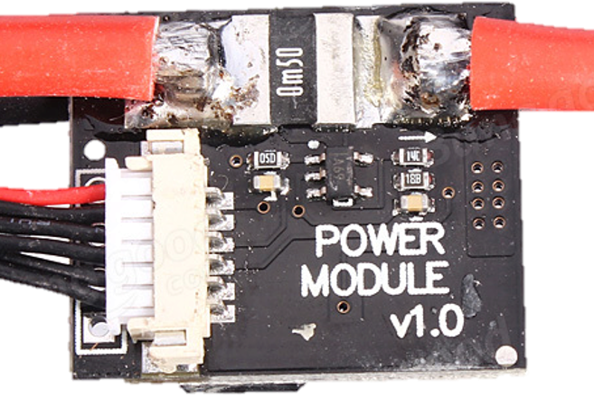
The Power Module GM V1.0 is a compact and reliable power supply module designed to provide stable voltage and current for a wide range of electronic circuits. It features built-in overcurrent protection and thermal shutdown, ensuring enhanced safety and durability. This module is ideal for powering microcontrollers, sensors, and other low-power devices in DIY projects, prototyping, and embedded systems.
Explore Projects Built with Power Module GM V1.0


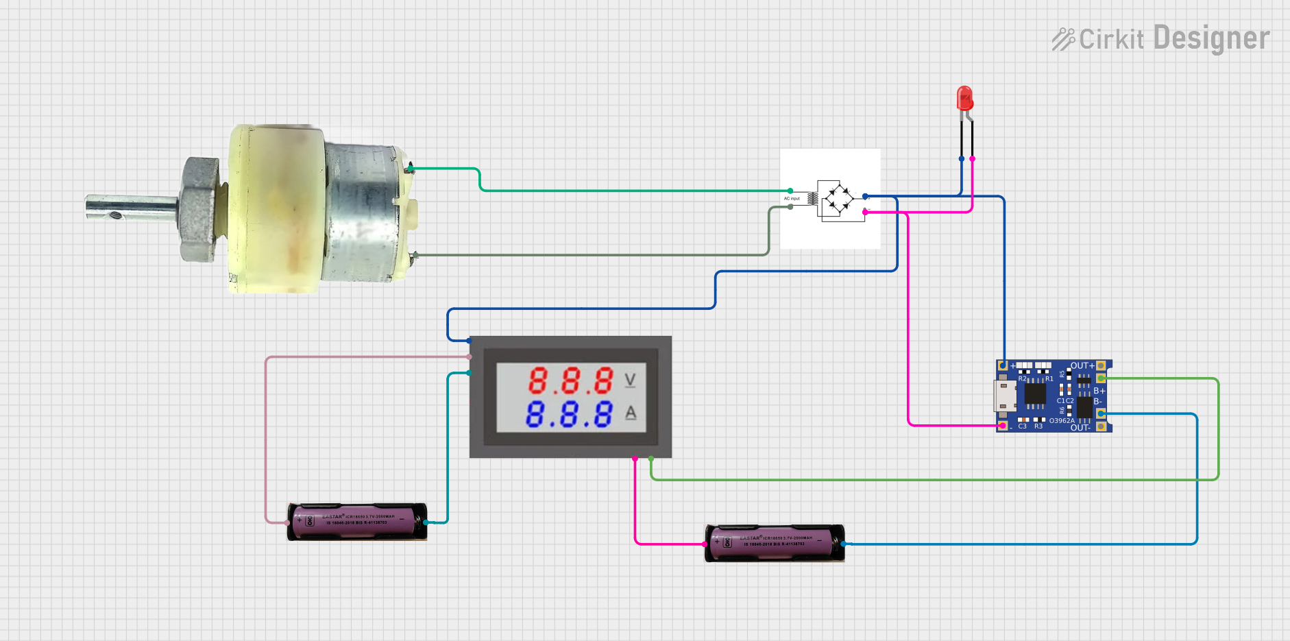
Explore Projects Built with Power Module GM V1.0
Common Applications and Use Cases
- Powering Arduino, Raspberry Pi, and other microcontroller boards
- Supplying stable voltage to sensors and actuators
- Prototyping low-power electronic circuits
- Educational and hobbyist electronics projects
- Battery-powered systems requiring regulated voltage
Technical Specifications
The Power Module GM V1.0 is designed to meet the needs of various low-power applications. Below are its key technical specifications:
| Parameter | Value |
|---|---|
| Input Voltage Range | 6V to 12V DC |
| Output Voltage | 5V DC (regulated) |
| Maximum Output Current | 1A |
| Efficiency | Up to 90% |
| Protection Features | Overcurrent protection, thermal shutdown |
| Dimensions | 25mm x 20mm x 10mm |
Pin Configuration and Descriptions
The module has three pins for input and output connections:
| Pin Name | Description |
|---|---|
| VIN | Input voltage (6V to 12V DC) |
| GND | Ground (common for input and output) |
| VOUT | Regulated 5V DC output |
Usage Instructions
How to Use the Power Module GM V1.0 in a Circuit
Connect the Input Voltage:
- Connect the VIN pin to a DC power source (6V to 12V).
- Ensure the power source can supply sufficient current for your application.
Connect the Ground:
- Connect the GND pin to the ground of your circuit. This serves as the common reference point.
Connect the Output Voltage:
- Use the VOUT pin to power your circuit with a stable 5V DC output.
Verify Connections:
- Double-check all connections to ensure proper polarity and avoid short circuits.
Power On:
- Turn on the input power source. The module will regulate the input voltage and provide a stable 5V output.
Important Considerations and Best Practices
- Input Voltage Range: Ensure the input voltage is within the specified range (6V to 12V). Exceeding this range may damage the module.
- Current Limitations: Do not exceed the maximum output current of 1A to prevent overheating or triggering the overcurrent protection.
- Heat Dissipation: If the module operates near its maximum current for extended periods, ensure adequate ventilation or use a heatsink to prevent thermal shutdown.
- Polarity: Always connect the input and output pins with the correct polarity to avoid damage.
Example: Using the Power Module GM V1.0 with an Arduino UNO
The Power Module GM V1.0 can be used to power an Arduino UNO. Below is an example of how to connect the module:
- Connect the VIN pin of the module to a 9V DC power source.
- Connect the GND pin of the module to the GND pin of the Arduino UNO.
- Connect the VOUT pin of the module to the 5V pin of the Arduino UNO.
Here is a simple Arduino sketch to blink an LED while powered by the module:
// Simple LED Blink Example
// This code blinks an LED connected to pin 13 of the Arduino UNO.
// Ensure the Power Module GM V1.0 is properly connected to the Arduino.

void setup() {
  pinMode(13, OUTPUT); // Set pin 13 as an output
}

void loop() {
  digitalWrite(13, HIGH); // Turn the LED on
  delay(1000);            // Wait for 1 second
  digitalWrite(13, LOW);  // Turn the LED off
  delay(1000);            // Wait for 1 second
}
Troubleshooting and FAQs
Common Issues and Solutions
No Output Voltage:
- Cause: Input voltage is not connected or is outside the specified range.
- Solution: Verify the input voltage is between 6V and 12V and check the connections.
Module Overheating:
- Cause: Excessive current draw or poor ventilation.
- Solution: Ensure the load does not exceed 1A and provide adequate ventilation or a heatsink.
Output Voltage Fluctuations:
- Cause: Unstable input voltage or excessive load.
- Solution: Use a stable DC power source and ensure the load is within the module's capacity.
Thermal Shutdown Triggered:
- Cause: Prolonged operation at high current or high ambient temperature.
- Solution: Reduce the load or improve cooling around the module.
FAQs
Q: Can I use the Power Module GM V1.0 with a 12V battery?
A: Yes, the module can be powered by a 12V battery as long as the current draw does not exceed 1A.
Q: Is the module suitable for powering a Raspberry Pi?
A: The module can power a Raspberry Pi Zero or similar low-power models. However, it may not provide sufficient current for higher-power Raspberry Pi models.
Q: What happens if I reverse the input polarity?
A: The module does not have reverse polarity protection. Reversing the input polarity may damage the module.
Q: Can I use this module to step up voltage?
A: No, the Power Module GM V1.0 is a step-down (buck) regulator and cannot increase the input voltage.