How to Use FR607: Examples, Pinouts, and Specs
Introduction
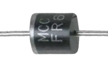
The FR607 is a fast recovery diode known for its high-speed switching capabilities and low reverse recovery time. It is designed to handle high current and voltage levels efficiently, making it an ideal choice for applications in power supplies, inverters, and other high-frequency electronic circuits.
Explore Projects Built with FR607


Explore Projects Built with FR607
Common Applications and Use Cases
- Switching power supplies
- Power management systems
- Inverters and converters
- Free-wheeling diodes in motor control circuits
- High-frequency rectification
Technical Specifications
Key Technical Details
| Parameter | Value |
|---|---|
| Peak Repetitive Reverse Voltage (Vrrm) | 1000 V |
| Average Rectified Forward Current (Io) | 6 A |
| Non-Repetitive Peak Forward Surge Current (Ifsm) | 150 A |
| Maximum Instantaneous Forward Voltage (Vf) | 1.3 V @ 3 A |
| Reverse Recovery Time (trr) | 500 ns |
| Operating Junction Temperature (Tj) | -65 to 150 °C |
Pin Configuration and Descriptions
The FR607 is a two-terminal device with the following pin configuration:
| Pin | Description |
|---|---|
| Anode (A) | The terminal through which the conventional current enters the diode. |
| Cathode (K) | The terminal through which the conventional current exits the diode. |
Usage Instructions
How to Use the FR607 in a Circuit
Orientation: Ensure the diode is oriented correctly in the circuit with the anode connected to the positive voltage and the cathode connected to the negative side or ground.
Current Rating: Do not exceed the average rectified forward current rating of 6 A to prevent overheating and potential damage.
Surge Current: Be mindful of the surge current rating during power-up or transient conditions.
Heat Management: Use appropriate heat sinking if operating at high currents or in high-temperature environments.
Reverse Voltage: Ensure that the reverse voltage does not exceed the peak repetitive reverse voltage rating of 1000 V.
Best Practices
- Use a current-limiting resistor or fuse to protect the diode from current spikes.
- Employ snubber circuits to minimize voltage transients that could exceed the diode's maximum ratings.
- Consider the reverse recovery time when designing high-frequency circuits to ensure efficient operation.
Troubleshooting and FAQs
Common Issues
- Diode not conducting: Check for correct orientation and ensure that the forward voltage is sufficient.
- Overheating: Verify that the current and power dissipation are within the specified limits.
- Unexpected voltage drops: Ensure that the diode is not subjected to a reverse voltage that exceeds its maximum rating.
Solutions and Tips for Troubleshooting
- If the diode fails to conduct, test it with a multimeter in diode mode to check for continuity.
- For overheating issues, improve heat dissipation with a better heat sink or by reducing the load current.
- Use a higher-rated diode if the reverse voltage spikes are causing breakdowns.
FAQs
Q: Can the FR607 be used for AC to DC conversion? A: Yes, the FR607 can be used in bridge rectifiers for AC to DC conversion due to its fast recovery time.
Q: Is it necessary to use a heat sink with the FR607? A: It depends on the current and operating conditions. If the diode operates near its maximum current rating or in a high-temperature environment, a heat sink is recommended.
Q: What is the significance of the reverse recovery time? A: The reverse recovery time affects the efficiency of the diode in high-frequency applications. A shorter recovery time means the diode can switch off faster, reducing power losses.
Q: Can I use the FR607 in a series configuration to increase the voltage rating? A: Yes, diodes can be connected in series to increase the overall voltage rating, but ensure that the reverse voltage is evenly distributed across each diode.
Example Connection with Arduino UNO
The FR607 can be used in conjunction with an Arduino UNO to create a simple rectifier circuit or to protect the microcontroller from reverse voltage transients.
// Example code to demonstrate the use of FR607 diode in a DC motor control circuit with Arduino UNO

const int motorPin = 3; // Connect the motor control pin to pin 3

void setup() {
  pinMode(motorPin, OUTPUT);
}

void loop() {
  digitalWrite(motorPin, HIGH); // Turn on the motor
  delay(1000);                  // Run the motor for 1 second
  digitalWrite(motorPin, LOW);  // Turn off the motor
  delay(1000);                  // Wait for 1 second
}

// Note: Connect the anode of the FR607 to the motor's positive terminal
// and the cathode to the Arduino's output pin. This setup provides
// flyback protection when the motor is turned off.
Remember to include a flyback diode like the FR607 when controlling inductive loads such as motors to prevent damage to the microcontroller from inductive voltage spikes.