How to Use XLR male: Examples, Pinouts, and Specs
Introduction
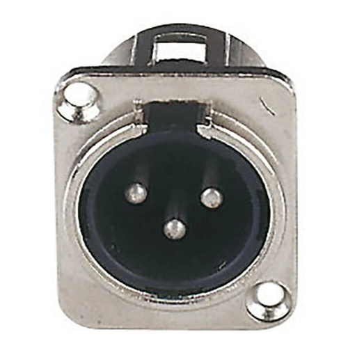
The XLR male connector is a type of electrical connector primarily found in professional audio, video, and stage lighting equipment. The connector is designed to provide a balanced audio signal, which helps to minimize noise and interference. XLR connectors are durable and have a locking mechanism that prevents accidental disconnection. They are commonly used for microphones, mixers, amplifiers, and other audio devices.
Explore Projects Built with XLR male


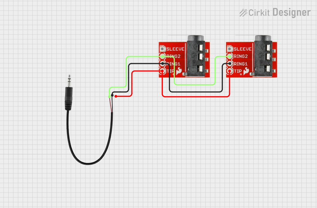
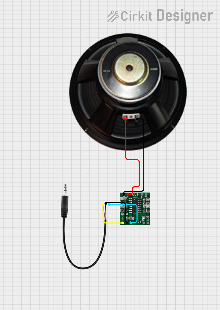
Explore Projects Built with XLR male
Common Applications and Use Cases
- Professional audio setups for live performances and recording studios
- Balanced microphone connections
- Audio interfaces and mixers
- DMX lighting control for stage lighting
- Interconnecting pro audio and video equipment
Technical Specifications
Key Technical Details
- Rated Voltage: Typically up to 250V
- Rated Current: Typically up to 16A
- Contact Resistance: Typically ≤ 5 mΩ
- Insulation Resistance: Typically > 1 GΩ
Pin Configuration and Descriptions
| Pin Number | Signal Connection | Description |
|---|---|---|
| 1 | Ground/Shield | Connected to the cable shield |
| 2 | Positive | Carries the positive phase signal |
| 3 | Negative | Carries the negative phase signal |
Usage Instructions
How to Use the Component in a Circuit
- Cable Preparation: Strip the audio cable to expose the shield and two conductors.
- Soldering: Solder the conductors and shield to the corresponding pins of the XLR male connector. Ensure good-quality solder joints to prevent signal loss or interference.
- Assembly: Once soldered, assemble the connector housing and secure it with screws or a locking mechanism provided.
- Testing: Test the connection with a multimeter to ensure continuity and correct polarity.
Important Considerations and Best Practices
- Always use balanced cables for connections to take full advantage of the noise rejection capabilities of the XLR connector.
- Ensure that the cable is properly shielded and that the shield is connected to pin 1.
- Avoid running audio cables parallel to power cables to minimize interference.
- Use strain relief to protect the cable and solder joints from tension and wear.
Troubleshooting and FAQs
Common Issues Users Might Face
- Intermittent Audio: This can be caused by poor solder joints or damaged cables. Check the connections and the cable for any signs of damage.
- No Audio: Ensure that the pins are correctly soldered to the corresponding cable conductors and that there is continuity between the connector and the cable.
- Noise or Hum: This can be due to improper grounding or a ground loop. Verify that the shield is properly connected to pin 1 and that there are no ground loops in the audio system.
Solutions and Tips for Troubleshooting
- Re-soldering: If a connection is weak or broken, re-solder the affected joint ensuring that the solder flows well and makes a solid connection.
- Cable Testing: Use a cable tester to check for continuity and correct wiring.
- Ground Loop Isolator: If a ground loop is suspected, use a ground loop isolator to break the loop and reduce hum.
FAQs
Q: Can I use an XLR male connector for unbalanced audio signals? A: Yes, but it is not recommended as you will not benefit from the noise rejection properties of a balanced connection.
Q: What is the difference between 3-pin and 5-pin XLR connectors? A: 3-pin XLR connectors are typically used for audio signals, while 5-pin versions are often used for lighting control (DMX) or stereo audio signals.
Q: How do I know if my XLR connector is wired correctly? A: Use a multimeter to check for continuity between the pins and the corresponding cable conductors. Pin 1 should connect to the shield, pin 2 to the positive conductor, and pin 3 to the negative conductor.
Q: Can XLR connectors be used for high-power applications? A: XLR connectors are not designed for high-power connections. They are intended for low-voltage audio and control signals.
Q: How do I clean an XLR connector? A: Use a dry cloth to wipe away any dust or debris. For more stubborn grime, use a small amount of isopropyl alcohol on a cloth or cotton swab to gently clean the contacts.