Cirkit Designer Logo
Cirkit Designer
Your all-in-one circuit design IDE
Home / 
Component Documentation

How to Use STC 1000: Examples, Pinouts, and Specs

Image of STC 1000
Cirkit Designer LogoDesign with STC 1000 in Cirkit Designer

Introduction

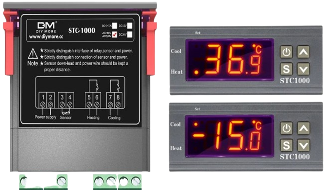
The STC 1000 is a versatile digital temperature controller manufactured by SMKN1KRAS (Part ID: A). It is widely used for regulating temperature in a variety of applications, including incubators, aquariums, fermentation chambers, and refrigeration systems. The device features a dual LED display for real-time temperature readings and supports both heating and cooling modes, making it ideal for maintaining precise temperature control.

Explore Projects Built with STC 1000

Use Cirkit Designer to design, explore, and prototype these projects online. Some projects support real-time simulation. Click "Open Project" to start designing instantly!
STM32F103C8T6-Based Spectral Sensor with ST7735S Display and Pushbutton Control
Image of ColorSensor: A project utilizing STC 1000 in a practical application
This circuit features an STM32F103C8T6 microcontroller interfaced with a China ST7735S 160x128 display and two spectral sensors (Adafruit AS7262 and AS7261). It also includes two pushbuttons for user input, with the microcontroller managing the display and sensor data processing.
Cirkit Designer LogoOpen Project in Cirkit Designer
STM32F103C8T6-Based Water Level Monitoring and Communication System with SIM900A and LoRa Connectivity
Image of water level: A project utilizing STC 1000 in a practical application
This circuit features a microcontroller (STM32F103C8T6) interfaced with a SIM900A GSM module, an HC-SR04 ultrasonic sensor, a water level sensor, and a LoRa Ra-02 SX1278 module for long-range communication. The STM32F103C8T6 is configured to communicate with the GSM module and LoRa module via serial connections, and it reads data from the ultrasonic and water level sensors. An FTDI Programmer is connected for programming and serial communication with the microcontroller.
Cirkit Designer LogoOpen Project in Cirkit Designer
Cellular-Enabled IoT Device with Real-Time Clock and Power Management
Image of LRCM PHASE 2 BASIC: A project utilizing STC 1000 in a practical application
This circuit features a LilyGo-SIM7000G module for cellular communication and GPS functionality, interfaced with an RTC DS3231 for real-time clock capabilities. It includes voltage sensing through two voltage sensor modules, and uses an 8-channel opto-coupler for isolating different parts of the circuit. Power management is handled by a buck converter connected to a DC power source and batteries, with a fuse for protection and a rocker switch for on/off control. Additionally, there's an LED for indication purposes.
Cirkit Designer LogoOpen Project in Cirkit Designer
STM32F103C8T6-Based Environmental Monitoring System with Multi-Sensor Integration
Image of NMKT: A project utilizing STC 1000 in a practical application
This circuit features an STM32F103C8T6 microcontroller as the central processing unit, interfacing with various sensors and output devices. It includes an MQ-4 methane gas sensor and an MQ135 air quality sensor for environmental monitoring, both connected to analog inputs. The circuit also controls a buzzer via a BC547 transistor, indicating certain conditions, and displays information on a 16x2 I2C LCD. Turbidity measurement is facilitated by a dedicated module, and a red LED indicates operational status or alerts, with resistors for current limiting and capacitors for power supply stabilization.
Cirkit Designer LogoOpen Project in Cirkit Designer

Explore Projects Built with STC 1000

Use Cirkit Designer to design, explore, and prototype these projects online. Some projects support real-time simulation. Click "Open Project" to start designing instantly!
Image of ColorSensor: A project utilizing STC 1000 in a practical application
STM32F103C8T6-Based Spectral Sensor with ST7735S Display and Pushbutton Control
This circuit features an STM32F103C8T6 microcontroller interfaced with a China ST7735S 160x128 display and two spectral sensors (Adafruit AS7262 and AS7261). It also includes two pushbuttons for user input, with the microcontroller managing the display and sensor data processing.
Cirkit Designer LogoOpen Project in Cirkit Designer
Image of water level: A project utilizing STC 1000 in a practical application
STM32F103C8T6-Based Water Level Monitoring and Communication System with SIM900A and LoRa Connectivity
This circuit features a microcontroller (STM32F103C8T6) interfaced with a SIM900A GSM module, an HC-SR04 ultrasonic sensor, a water level sensor, and a LoRa Ra-02 SX1278 module for long-range communication. The STM32F103C8T6 is configured to communicate with the GSM module and LoRa module via serial connections, and it reads data from the ultrasonic and water level sensors. An FTDI Programmer is connected for programming and serial communication with the microcontroller.
Cirkit Designer LogoOpen Project in Cirkit Designer
Image of LRCM PHASE 2 BASIC: A project utilizing STC 1000 in a practical application
Cellular-Enabled IoT Device with Real-Time Clock and Power Management
This circuit features a LilyGo-SIM7000G module for cellular communication and GPS functionality, interfaced with an RTC DS3231 for real-time clock capabilities. It includes voltage sensing through two voltage sensor modules, and uses an 8-channel opto-coupler for isolating different parts of the circuit. Power management is handled by a buck converter connected to a DC power source and batteries, with a fuse for protection and a rocker switch for on/off control. Additionally, there's an LED for indication purposes.
Cirkit Designer LogoOpen Project in Cirkit Designer
Image of NMKT: A project utilizing STC 1000 in a practical application
STM32F103C8T6-Based Environmental Monitoring System with Multi-Sensor Integration
This circuit features an STM32F103C8T6 microcontroller as the central processing unit, interfacing with various sensors and output devices. It includes an MQ-4 methane gas sensor and an MQ135 air quality sensor for environmental monitoring, both connected to analog inputs. The circuit also controls a buzzer via a BC547 transistor, indicating certain conditions, and displays information on a 16x2 I2C LCD. Turbidity measurement is facilitated by a dedicated module, and a red LED indicates operational status or alerts, with resistors for current limiting and capacitors for power supply stabilization.
Cirkit Designer LogoOpen Project in Cirkit Designer

Common Applications

  • Incubators for hatching eggs
  • Homebrewing and fermentation chambers
  • Aquariums and terrariums
  • Refrigeration systems
  • Greenhouses and environmental chambers

Technical Specifications

Key Technical Details

Parameter Value
Operating Voltage AC 110V-220V ±10%
Temperature Range -50°C to 99°C (-58°F to 210°F)
Temperature Accuracy ±1°C
Sensor Type NTC (10kΩ) Thermistor
Relay Output Capacity Heating: 10A/220V AC
Cooling: 10A/220V AC
Power Consumption ≤3W
Operating Temperature -10°C to 60°C
Storage Temperature -20°C to 75°C
Dimensions 75mm x 34.5mm x 85mm

Pin Configuration and Descriptions

The STC 1000 has a total of 8 terminals for wiring. Below is the pin configuration:

Terminal Number Description
1 Power Input (Live/Hot, AC 110-220V)
2 Power Input (Neutral, AC 110-220V)
3 Cooling Device Output (Live)
4 Cooling Device Output (Neutral)
5 Heating Device Output (Live)
6 Heating Device Output (Neutral)
7 Temperature Sensor Input (NTC)
8 Temperature Sensor Input (NTC)

Usage Instructions

How to Use the STC 1000 in a Circuit

  1. Wiring the Power Supply: Connect terminals 1 and 2 to the AC power source (110-220V). Ensure proper polarity (live and neutral).
  2. Connecting the Temperature Sensor: Attach the NTC thermistor sensor to terminals 7 and 8. Place the sensor in the environment where temperature regulation is required.
  3. Connecting Heating and Cooling Devices:
    • Connect the heating device to terminals 5 and 6.
    • Connect the cooling device to terminals 3 and 4.
  4. Configuring the Temperature Settings:
    • Power on the device.
    • Use the "Set" button to enter the configuration menu.
    • Adjust the desired temperature setpoint and hysteresis (temperature difference for switching).
  5. Testing the System: Verify that the heating and cooling devices activate and deactivate as per the set temperature thresholds.

Important Considerations and Best Practices

  • Ensure all connections are secure and insulated to prevent electrical hazards.
  • Use appropriate fuses or circuit breakers to protect the device and connected equipment.
  • Avoid placing the temperature sensor near heat sources or in direct sunlight for accurate readings.
  • Regularly clean the sensor to maintain accuracy.
  • Do not exceed the relay output capacity (10A/220V) to avoid damage.

Example: Using the STC 1000 with an Arduino UNO

While the STC 1000 is a standalone device, it can be integrated with an Arduino UNO for advanced monitoring or automation. Below is an example code snippet to read the temperature data from the STC 1000's sensor (NTC thermistor):

// Example code to read temperature from an NTC thermistor
// connected to an analog pin on the Arduino UNO

const int sensorPin = A0; // Analog pin connected to the NTC thermistor
float resistance;         // Variable to store resistance value
float temperature;        // Variable to store calculated temperature

void setup() {
  Serial.begin(9600); // Initialize serial communication
}

void loop() {
  int sensorValue = analogRead(sensorPin); // Read analog value from sensor
  resistance = (1023.0 / sensorValue - 1) * 10000; 
  // Convert analog value to resistance (assuming 10k pull-up resistor)

  // Calculate temperature in Celsius using the Steinhart-Hart equation
  float steinhart;
  steinhart = resistance / 10000.0; // (R/Ro)
  steinhart = log(steinhart);       // ln(R/Ro)
  steinhart /= 3950.0;              // 1/B * ln(R/Ro)
  steinhart += 1.0 / (25.0 + 273.15); // + (1/To)
  steinhart = 1.0 / steinhart;      // Invert
  temperature = steinhart - 273.15; // Convert to Celsius

  Serial.print("Temperature: ");
  Serial.print(temperature);
  Serial.println(" °C");

  delay(1000); // Wait 1 second before next reading
}

Note: The above code assumes a 10kΩ pull-up resistor and a B-value of 3950 for the NTC thermistor. Adjust these values based on your specific sensor.

Troubleshooting and FAQs

Common Issues and Solutions

  1. Device Does Not Power On:

    • Check the power supply voltage (110-220V AC).
    • Ensure proper wiring to terminals 1 and 2.
  2. Incorrect Temperature Readings:

    • Verify the sensor is properly connected to terminals 7 and 8.
    • Ensure the sensor is not damaged or placed in an unsuitable location.
  3. Heating or Cooling Devices Not Activating:

    • Check the relay output connections (terminals 3-6).
    • Ensure the devices are functional and within the relay's capacity (10A/220V).
  4. Temperature Fluctuations:

    • Adjust the hysteresis setting to reduce frequent switching.
    • Ensure the sensor is not exposed to rapid environmental changes.

FAQs

Q: Can the STC 1000 be used with DC-powered devices?
A: No, the STC 1000 is designed for AC-powered devices only. Use a DC-AC relay or converter if necessary.

Q: What is the maximum cable length for the temperature sensor?
A: The sensor cable can typically be extended up to 10 meters, but ensure proper shielding to avoid interference.

Q: Can I use the STC 1000 for sub-zero temperature applications?
A: Yes, the STC 1000 supports temperatures as low as -50°C, making it suitable for cold storage applications.

Q: How do I reset the STC 1000 to factory settings?
A: Press and hold the "Set" button for 5 seconds while powering on the device to reset it.

By following this documentation, users can effectively utilize the STC 1000 for precise temperature control in various applications.