
How to Use AC Light Dimmer 4-Channel Thyristor Triac Speed Controller Dimmer 220V AC: Examples, Pinouts, and Specs
 Design with AC Light Dimmer 4-Channel Thyristor Triac Speed Controller Dimmer 220V AC in Cirkit Designer
Introduction
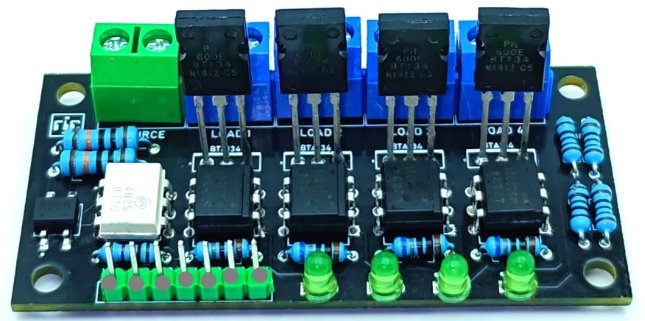
The AC Light Dimmer 4-Channel Thyristor Triac Speed Controller Dimmer 220V AC, manufactured by Dimmer, is a versatile device designed to control the brightness of lights or the speed of AC motors. It achieves this by regulating the power delivered to the connected load using thyristor and triac technology. This component is ideal for applications requiring precise control of AC power, such as home lighting systems, industrial motor speed control, and stage lighting.
Explore Projects Built with AC Light Dimmer 4-Channel Thyristor Triac Speed Controller Dimmer 220V AC
 Open Project in Cirkit Designer
 Open Project in Cirkit Designer
 Open Project in Cirkit Designer
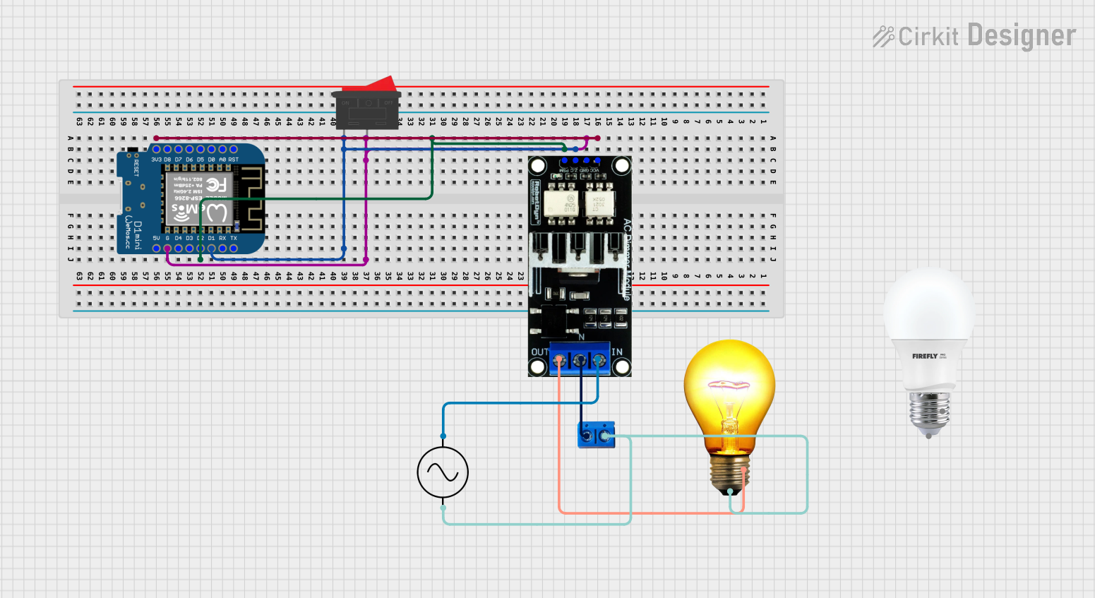 Open Project in Cirkit Designer
Explore Projects Built with AC Light Dimmer 4-Channel Thyristor Triac Speed Controller Dimmer 220V AC
Open Project in Cirkit DesignerOpen Project in Cirkit DesignerOpen Project in Cirkit DesignerOpen Project in Cirkit DesignerCommon Applications
- Dimming incandescent or halogen lights
- Speed control for AC motors (e.g., fans, pumps)
- Stage lighting and theatrical effects
- Energy-saving systems in residential and commercial environments
Technical Specifications
Below are the key technical details of the AC Light Dimmer:
| Parameter | Value |
|---|---|
| Input Voltage | 220V AC |
| Output Voltage Range | 0V to 220V AC (adjustable) |
| Channels | 4 |
| Control Method | Thyristor and Triac |
| Maximum Load per Channel | 2A |
| Total Maximum Load | 8A |
| Frequency | 50Hz / 60Hz |
| Isolation | Optocoupler-based isolation |
| Dimensions | 100mm x 80mm x 25mm |
| Operating Temperature | -10°C to 50°C |
Pin Configuration and Descriptions
The dimmer module has multiple input and output terminals for control and load connections. Below is the pin configuration:
Input Terminals
| Pin Name | Description |
|---|---|
| AC_L | Live input from the 220V AC power source |
| AC_N | Neutral input from the 220V AC power source |
| CH1_CTRL | Control signal input for Channel 1 (PWM or analog) |
| CH2_CTRL | Control signal input for Channel 2 (PWM or analog) |
| CH3_CTRL | Control signal input for Channel 3 (PWM or analog) |
| CH4_CTRL | Control signal input for Channel 4 (PWM or analog) |
Output Terminals
| Pin Name | Description |
|---|---|
| CH1_OUT | Output for Channel 1 (connect to load) |
| CH2_OUT | Output for Channel 2 (connect to load) |
| CH3_OUT | Output for Channel 3 (connect to load) |
| CH4_OUT | Output for Channel 4 (connect to load) |
Usage Instructions
How to Use the Component in a Circuit
- Power Connection: Connect the AC_L and AC_N terminals to the live and neutral wires of the 220V AC power source.
- Load Connection: Connect the load (e.g., light bulb or motor) to the corresponding output terminals (e.g., CH1_OUT, CH2_OUT).
- Control Signal: Provide a control signal (PWM or analog voltage) to the control input pins (e.g., CH1_CTRL, CH2_CTRL). This signal determines the power delivered to the load.
- Isolation: Ensure proper electrical isolation between the control circuit and the AC power circuit to prevent damage or hazards.
Important Considerations
- Load Compatibility: Ensure the connected load does not exceed the maximum current rating of 2A per channel.
- Heat Dissipation: The module may generate heat during operation. Use proper ventilation or a heatsink if necessary.
- Safety Precautions: Always handle the module with care when connected to high-voltage AC power. Disconnect power before making any changes to the wiring.
- Control Signal: For Arduino or microcontroller-based control, use a PWM signal with a frequency between 100Hz and 1kHz.
Example: Using with Arduino UNO
Below is an example of how to control one channel of the dimmer using an Arduino UNO:
// Example code to control AC Light Dimmer using Arduino UNO
// This code generates a PWM signal to control the brightness of a light

#define DIMMER_PIN 9  // PWM pin connected to CH1_CTRL

void setup() {
  pinMode(DIMMER_PIN, OUTPUT);  // Set the pin as output
}

void loop() {
  for (int brightness = 0; brightness <= 255; brightness++) {
    analogWrite(DIMMER_PIN, brightness);  // Increase brightness gradually
    delay(10);  // Delay for smooth dimming
  }
  for (int brightness = 255; brightness >= 0; brightness--) {
    analogWrite(DIMMER_PIN, brightness);  // Decrease brightness gradually
    delay(10);  // Delay for smooth dimming
  }
}
Troubleshooting and FAQs
Common Issues and Solutions
No Output from the Dimmer
- Cause: Incorrect wiring or no control signal.
- Solution: Verify that the AC_L and AC_N terminals are connected to a live 220V AC source. Check the control signal input.
Flickering Lights
- Cause: Incompatible load or incorrect PWM frequency.
- Solution: Ensure the load is compatible with dimming (e.g., incandescent or dimmable LED). Use a PWM frequency between 100Hz and 1kHz.
Overheating
- Cause: Exceeding the maximum load current or poor ventilation.
- Solution: Reduce the load or improve ventilation around the module.
Control Signal Not Responding
- Cause: Faulty microcontroller or incorrect pin configuration.
- Solution: Verify the microcontroller's output pin and ensure it is properly connected to the dimmer's control input.
FAQs
Q: Can this dimmer be used with non-dimmable LED lights?
A: No, this dimmer is not compatible with non-dimmable LED lights. Use only dimmable LEDs or incandescent bulbs.
Q: What happens if I exceed the maximum load per channel?
A: Exceeding the maximum load can damage the module or cause overheating. Always stay within the specified limits.
Q: Can I control all four channels independently?
A: Yes, each channel has its own control input, allowing independent operation.
Q: Is this module suitable for 110V AC systems?
A: No, this module is designed specifically for 220V AC systems. Use a compatible dimmer for 110V AC applications.