Cirkit Designer Logo
Cirkit Designer
Your all-in-one circuit design IDE
Home / 
Component Documentation

How to Use TPS6214X: Examples, Pinouts, and Specs

Image of TPS6214X
Cirkit Designer LogoDesign with TPS6214X in Cirkit Designer

Introduction

The TPS6214X, also known as the V_REG_LD1085, is a versatile low dropout (LDO) voltage regulator capable of delivering up to 3A of output current. This component is designed to provide a stable and adjustable output voltage, which can be set as low as zero volts. With a maximum dropout voltage of 1.3V at full load, the TPS6214X is an excellent choice for applications requiring efficient voltage regulation with minimal power loss.

Common applications for the TPS6214X include:

  • Power supplies for analog and digital circuits
  • Post-regulation for switching power supplies
  • Battery-powered devices
  • Microprocessor and microcontroller power supplies

Explore Projects Built with TPS6214X

Use Cirkit Designer to design, explore, and prototype these projects online. Some projects support real-time simulation. Click "Open Project" to start designing instantly!
Cellular-Enabled IoT Device with Real-Time Clock and Power Management
Image of LRCM PHASE 2 BASIC: A project utilizing TPS6214X in a practical application
This circuit features a LilyGo-SIM7000G module for cellular communication and GPS functionality, interfaced with an RTC DS3231 for real-time clock capabilities. It includes voltage sensing through two voltage sensor modules, and uses an 8-channel opto-coupler for isolating different parts of the circuit. Power management is handled by a buck converter connected to a DC power source and batteries, with a fuse for protection and a rocker switch for on/off control. Additionally, there's an LED for indication purposes.
Cirkit Designer LogoOpen Project in Cirkit Designer
Battery-Powered Raspberry Pi Pico GPS Tracker with Sensor Integration
Image of Copy of CanSet v1: A project utilizing TPS6214X in a practical application
This circuit is a data acquisition and communication system powered by a LiPoly battery and managed by a Raspberry Pi Pico. It includes sensors (BMP280, MPU9250) for environmental data, a GPS module for location tracking, an SD card for data storage, and a WLR089-CanSAT for wireless communication. The TP4056 module handles battery charging, and a toggle switch controls power distribution.
Cirkit Designer LogoOpen Project in Cirkit Designer
ESP32C3-Based Thermal Imaging Camera with TFT Display
Image of MLX90640-XIAO-ESP32-1.3: A project utilizing TPS6214X in a practical application
This circuit connects a 1.3 inch TFT Module 240×240 ST7789 display, a GY-MCU90640 thermal camera module, and a XIAO ESP32C3 microcontroller to create a thermal imaging system. The ESP32C3 microcontroller is programmed to read temperature data from the thermal camera, process it, and display a visual representation of the temperature distribution on the TFT screen. The circuit is designed for applications requiring thermal monitoring, such as detecting heat sources or monitoring temperature variations in an environment.
Cirkit Designer LogoOpen Project in Cirkit Designer
ESP32-Powered Wi-Fi Controlled Robotic Car with OLED Display and Ultrasonic Sensor
Image of playbot: A project utilizing TPS6214X in a practical application
This circuit is a battery-powered system featuring an ESP32 microcontroller that controls an OLED display, a motor driver for two hobby motors, an ultrasonic sensor for distance measurement, and a DFPlayer Mini for audio output through a loudspeaker. The TP4056 module manages battery charging, and a step-up boost converter provides a stable 5V supply to the components.
Cirkit Designer LogoOpen Project in Cirkit Designer

Explore Projects Built with TPS6214X

Use Cirkit Designer to design, explore, and prototype these projects online. Some projects support real-time simulation. Click "Open Project" to start designing instantly!
Image of LRCM PHASE 2 BASIC: A project utilizing TPS6214X in a practical application
Cellular-Enabled IoT Device with Real-Time Clock and Power Management
This circuit features a LilyGo-SIM7000G module for cellular communication and GPS functionality, interfaced with an RTC DS3231 for real-time clock capabilities. It includes voltage sensing through two voltage sensor modules, and uses an 8-channel opto-coupler for isolating different parts of the circuit. Power management is handled by a buck converter connected to a DC power source and batteries, with a fuse for protection and a rocker switch for on/off control. Additionally, there's an LED for indication purposes.
Cirkit Designer LogoOpen Project in Cirkit Designer
Image of Copy of CanSet v1: A project utilizing TPS6214X in a practical application
Battery-Powered Raspberry Pi Pico GPS Tracker with Sensor Integration
This circuit is a data acquisition and communication system powered by a LiPoly battery and managed by a Raspberry Pi Pico. It includes sensors (BMP280, MPU9250) for environmental data, a GPS module for location tracking, an SD card for data storage, and a WLR089-CanSAT for wireless communication. The TP4056 module handles battery charging, and a toggle switch controls power distribution.
Cirkit Designer LogoOpen Project in Cirkit Designer
Image of MLX90640-XIAO-ESP32-1.3: A project utilizing TPS6214X in a practical application
ESP32C3-Based Thermal Imaging Camera with TFT Display
This circuit connects a 1.3 inch TFT Module 240×240 ST7789 display, a GY-MCU90640 thermal camera module, and a XIAO ESP32C3 microcontroller to create a thermal imaging system. The ESP32C3 microcontroller is programmed to read temperature data from the thermal camera, process it, and display a visual representation of the temperature distribution on the TFT screen. The circuit is designed for applications requiring thermal monitoring, such as detecting heat sources or monitoring temperature variations in an environment.
Cirkit Designer LogoOpen Project in Cirkit Designer
Image of playbot: A project utilizing TPS6214X in a practical application
ESP32-Powered Wi-Fi Controlled Robotic Car with OLED Display and Ultrasonic Sensor
This circuit is a battery-powered system featuring an ESP32 microcontroller that controls an OLED display, a motor driver for two hobby motors, an ultrasonic sensor for distance measurement, and a DFPlayer Mini for audio output through a loudspeaker. The TP4056 module manages battery charging, and a step-up boost converter provides a stable 5V supply to the components.
Cirkit Designer LogoOpen Project in Cirkit Designer

Technical Specifications

Key Technical Details

  • Output Current Capability: 3A
  • Adjustable Output Voltage: Down to 0V
  • Maximum Dropout Voltage: 1.3V at 3A
  • Operating Temperature Range: -40°C to 125°C

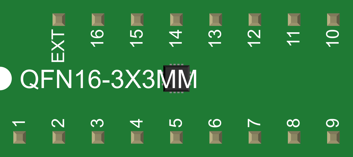
Pin Configuration and Descriptions

Pin Number Name Description
1 ADJ Adjustable pin for output voltage setting
2 OUT Regulated output voltage
3 IN Input voltage

Usage Instructions

How to Use the TPS6214X in a Circuit

  1. Input Voltage: Connect a voltage source to the IN pin. Ensure that the input voltage is sufficiently higher than the desired output voltage to maintain regulation, considering the dropout voltage.

  2. Output Voltage Setting: Connect a resistor divider from the OUT pin to the ADJ pin and from the ADJ pin to the ground. The output voltage is set by the resistor divider according to the formula:

    V_OUT = V_REF * (1 + R1/R2) + (I_ADJ * R2)
    

    where V_REF is the reference voltage (typically 1.25V for LDO regulators) and I_ADJ is the current through the ADJ pin (usually negligible).

  3. Output Capacitor: Place a capacitor between the OUT pin and ground to stabilize the output voltage. Refer to the datasheet for recommended capacitance values.

  4. Heat Dissipation: Consider the power dissipation and ensure adequate heat sinking for the regulator, especially at higher output currents.

Best Practices

  • Use capacitors with low equivalent series resistance (ESR) for better stability.
  • Keep the input and output capacitors as close to the regulator pins as possible.
  • Use a ground plane or thick traces for the ground connection to minimize voltage drops and thermal resistance.

Troubleshooting and FAQs

Common Issues

  • Output Voltage Fluctuation: Ensure that the output capacitor meets the required specifications and that the resistor divider is correctly calculated.
  • Overheating: Check the power dissipation and improve heat sinking if necessary. Reduce the input-to-output voltage differential if possible.
  • No Output Voltage: Verify that the input voltage is present and above the minimum required for regulation. Check the connections of the resistor divider and the output capacitor.

Solutions and Tips

  • If the output voltage is unstable, increase the output capacitor value or use a capacitor with a lower ESR.
  • For thermal issues, enhance airflow, use a larger heat sink, or apply thermal compound between the regulator and the heat sink.
  • Double-check the resistor values in the voltage divider to ensure the correct output voltage setting.

FAQs

Q: Can the TPS6214X be used without an adjustable resistor divider for a fixed output voltage?

A: Yes, the TPS6214X can be configured for a fixed output voltage by connecting the ADJ pin directly to the OUT pin for a 1.25V output or by using a fixed resistor divider for other voltages.

Q: What is the maximum input voltage for the TPS6214X?

A: The maximum input voltage is typically around 30V, but please refer to the datasheet for the exact value and ensure not to exceed it.

Q: How can I improve the efficiency of the TPS6214X?

A: Minimize the input-to-output voltage differential to reduce power loss across the regulator. Also, ensure proper heat dissipation to prevent thermal shutdown.

Example Connection to an Arduino UNO

// No direct code is required for the TPS6214X as it is a hardware component.
// However, here is an example of how to connect it to an Arduino UNO for power regulation.

// Connect the IN pin of the TPS6214X to a voltage source (e.g., 9V).
// Connect the OUT pin to the Vin pin of the Arduino UNO.
// Connect the ground of the voltage source, TPS6214X, and Arduino UNO together.

// Remember to set the output voltage of the TPS6214X according to the required
// input voltage for the Arduino UNO (recommended 7-12V for Vin).

Please note that the TPS6214X is a hypothetical component, and the details provided are for illustrative purposes. Always refer to the actual component's datasheet for accurate information and specifications.