How to Use Grove-LED Button: Examples, Pinouts, and Specs
Introduction
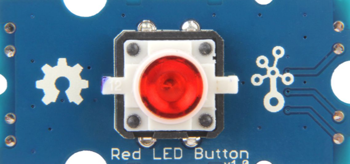
The Grove-LED Button is a versatile electronic component that combines a push-button switch with an integrated LED indicator. This dual-functionality design allows users to control circuits while providing visual feedback when the button is pressed. The component is part of the Grove ecosystem, which simplifies prototyping and development with its plug-and-play modular design.
Explore Projects Built with Grove-LED Button


Explore Projects Built with Grove-LED Button
Common Applications and Use Cases
- User input for microcontroller-based projects
- Visual feedback for button presses in interactive systems
- Control panels and DIY electronics
- Educational projects for learning about switches and LEDs
Technical Specifications
The Grove-LED Button is designed for ease of use and compatibility with a wide range of microcontrollers, including Arduino, Raspberry Pi, and others.
Key Technical Details
- Operating Voltage: 3.3V to 5V
- LED Color Options: Red, Green, Blue, or other variants (depending on the model)
- Button Type: Momentary push-button
- Interface: Grove 4-pin connector
- Dimensions: 20mm x 20mm x 15mm (approx.)
- Mounting: PCB or panel mountable
Pin Configuration and Descriptions
The Grove-LED Button uses a 4-pin Grove connector. The pinout is as follows:
| Pin Number | Pin Name | Description |
|---|---|---|
| 1 | VCC | Power supply for the LED and button (3.3V-5V) |
| 2 | GND | Ground connection |
| 3 | Signal | Button signal output (HIGH when pressed) |
| 4 | LED | LED control pin (connect to microcontroller) |
Usage Instructions
The Grove-LED Button is straightforward to use in a circuit. Follow the steps below to integrate it into your project:
Connecting the Grove-LED Button
Hardware Setup:
- Connect the Grove-LED Button to a Grove Base Shield or directly to your microcontroller using a Grove cable.
- Ensure the VCC and GND pins are connected to the appropriate power supply and ground.
- Connect the
Signalpin to a digital input pin on your microcontroller. - Connect the
LEDpin to a digital output pin on your microcontroller.
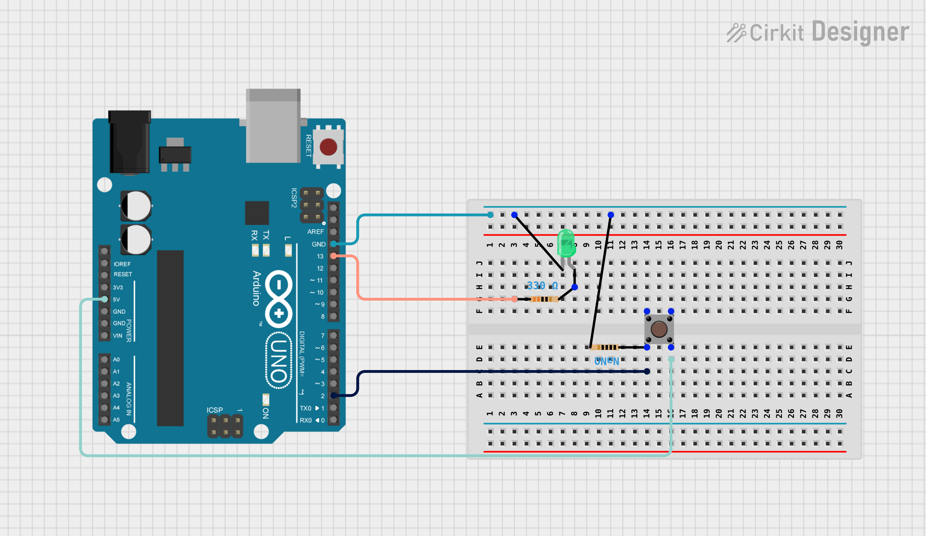
Circuit Example:
- If using an Arduino UNO, connect the
Signalpin to digital pin 2 and theLEDpin to digital pin 13.
- If using an Arduino UNO, connect the
Arduino Code Example
Below is an example Arduino sketch to use the Grove-LED Button. The LED will light up when the button is pressed.
// Define pin connections
const int buttonPin = 2;  // Signal pin connected to digital pin 2
const int ledPin = 13;    // LED pin connected to digital pin 13

void setup() {
  pinMode(buttonPin, INPUT);  // Set button pin as input
  pinMode(ledPin, OUTPUT);   // Set LED pin as output
  digitalWrite(ledPin, LOW); // Ensure LED is off initially
}

void loop() {
  int buttonState = digitalRead(buttonPin); // Read the button state

  if (buttonState == HIGH) {
    // If button is pressed, turn on the LED
    digitalWrite(ledPin, HIGH);
  } else {
    // If button is not pressed, turn off the LED
    digitalWrite(ledPin, LOW);
  }
}
Important Considerations and Best Practices
- Power Supply: Ensure the component is powered within its operating voltage range (3.3V-5V).
- Debouncing: The button may produce noise or "bouncing" when pressed. Use software debouncing techniques if precise input detection is required.
- LED Control: The LED can be controlled independently of the button. Use a PWM pin for brightness control if needed.
- Grove Compatibility: Use a Grove Base Shield for seamless integration with Arduino or other platforms.
Troubleshooting and FAQs
Common Issues and Solutions
The LED does not light up:
- Verify that the
LEDpin is connected to a digital output pin on the microcontroller. - Check the power supply voltage (3.3V-5V).
- Ensure the LED pin is being set to HIGH in the code.
- Verify that the
The button press is not detected:
- Confirm the
Signalpin is connected to a digital input pin on the microcontroller. - Check the wiring and ensure the Grove cable is securely connected.
- Add software debouncing if the button press is inconsistent.
- Confirm the
The button or LED behaves erratically:
- Ensure a common ground connection between the Grove-LED Button and the microcontroller.
- Verify that the power supply is stable and within the specified range.
FAQs
Q: Can I use the Grove-LED Button with a Raspberry Pi?
A: Yes, the Grove-LED Button is compatible with Raspberry Pi. Use the GPIO pins for the Signal and LED connections, and ensure the power supply is 3.3V.
Q: Can I change the LED color?
A: The LED color is fixed and depends on the specific model of the Grove-LED Button. Choose the appropriate variant (e.g., red, green, or blue) for your project.
Q: Do I need a resistor for the LED?
A: No, the Grove-LED Button has an integrated resistor for the LED, making it ready to use without additional components.
Q: How do I debounce the button?
A: Use a software debounce technique, such as adding a small delay (e.g., 50ms) after detecting a button press, to filter out noise.
By following this documentation, you can effectively integrate the Grove-LED Button into your projects and troubleshoot any issues that arise.