How to Use SSR: Examples, Pinouts, and Specs
Introduction
A Solid State Relay (SSR) is an electronic switching device that uses semiconductor components, such as thyristors, triacs, or transistors, to perform switching operations. Unlike mechanical relays, SSRs have no moving parts, which allows for faster switching speeds, silent operation, and significantly longer operational life. SSRs are widely used in applications where high reliability, noise-free operation, and fast switching are required.
Explore Projects Built with SSR


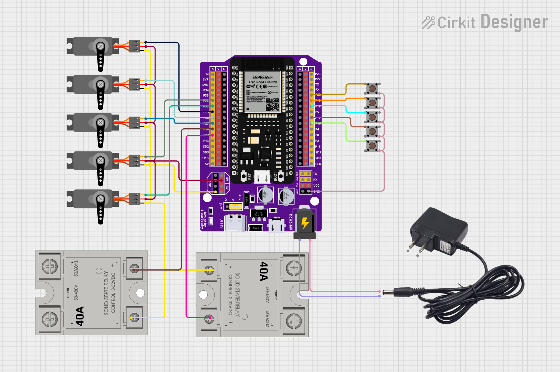
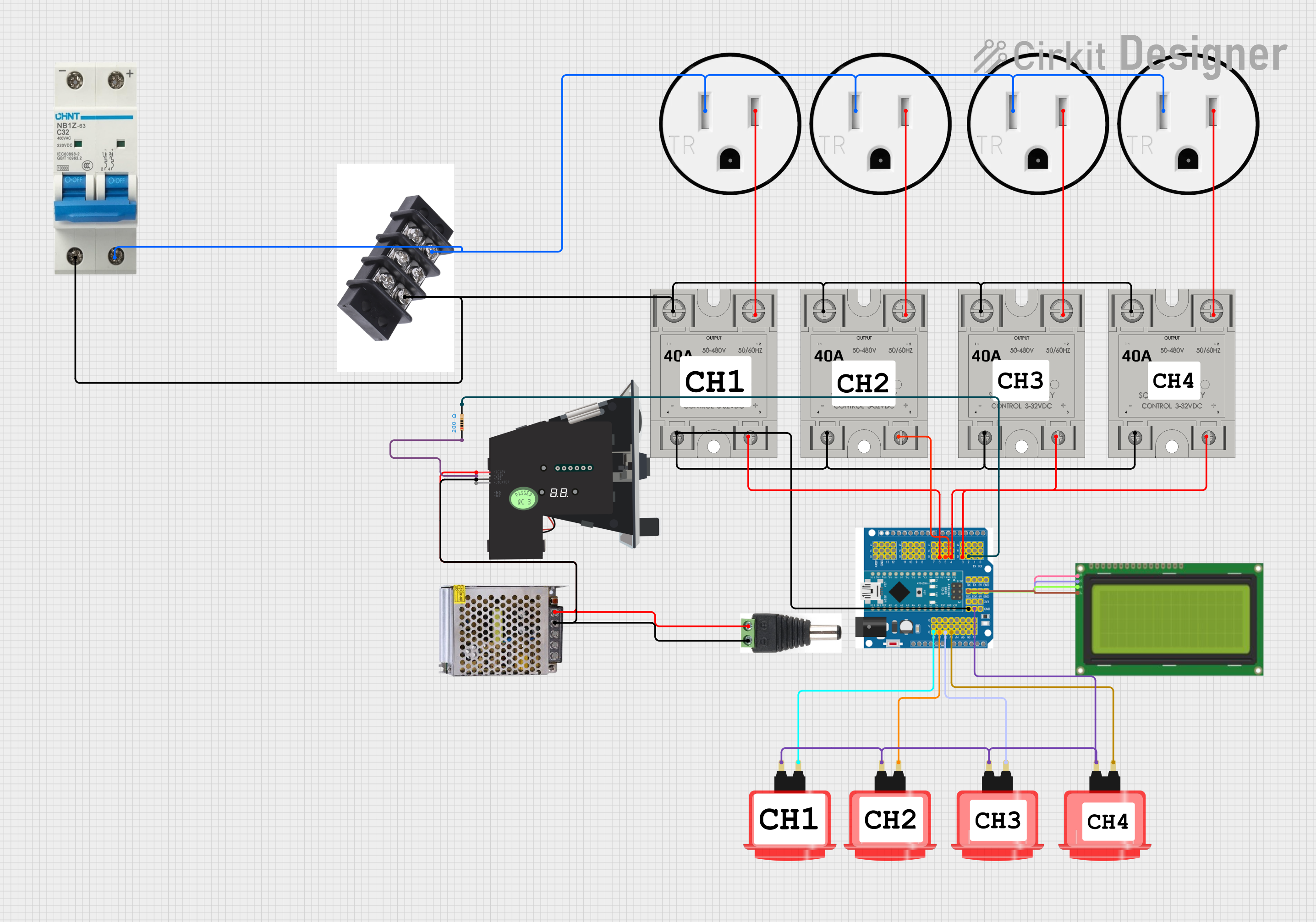
Explore Projects Built with SSR
Common Applications and Use Cases
- Industrial automation and control systems
- Heating, ventilation, and air conditioning (HVAC) systems
- Motor control and power distribution
- Lighting control systems
- Home appliances and smart home devices
- Temperature control in ovens and furnaces
Technical Specifications
Below are the general technical specifications for a typical SSR. Note that specific values may vary depending on the model and manufacturer.
Key Technical Details
- Input Voltage (Control Signal): 3–32 VDC or 90–280 VAC (depending on SSR type)
- Output Voltage (Load): 24–480 VAC or 24–200 VDC
- Load Current Rating: 2 A to 100 A (varies by model)
- Switching Speed: Typically <10 ms
- Isolation Voltage: 2500–4000 V (between input and output)
- Operating Temperature Range: -30°C to +80°C
- Dielectric Strength: 2.5 kV or higher
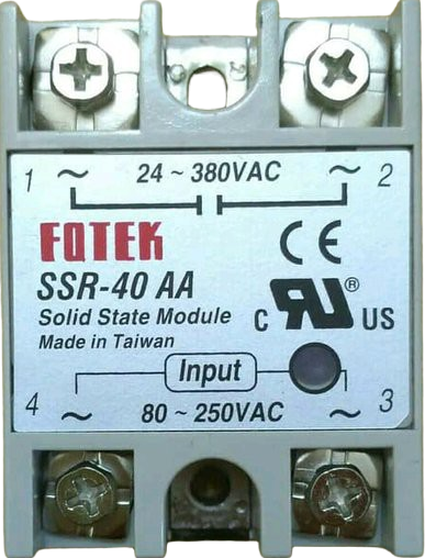
Pin Configuration and Descriptions
The pin configuration of an SSR typically includes input (control) terminals and output (load) terminals. Below is a table describing the common pinout:
| Pin Number | Name | Description |
|---|---|---|
| 1 | Input (+) | Positive terminal for the control signal (e.g., from a microcontroller). |
| 2 | Input (-) | Negative terminal for the control signal (ground). |
| 3 | Load Terminal 1 | One terminal of the load circuit (connected to the AC or DC load). |
| 4 | Load Terminal 2 | The other terminal of the load circuit (connected to the AC or DC power). |
Note: Some SSRs may have additional pins for features like status indicators or zero-crossing detection.
Usage Instructions
How to Use the Component in a Circuit
Connect the Control Signal:
- Connect the positive control signal (e.g., from a microcontroller or external power source) to the Input (+) terminal.
- Connect the ground of the control signal to the Input (-) terminal.
- Ensure the control signal voltage is within the SSR's input voltage range.
Connect the Load Circuit:
- Connect one terminal of the load (e.g., a motor, light, or heater) to Load Terminal 1.
- Connect the other terminal of the load to the power source (AC or DC, depending on the SSR type).
- Connect Load Terminal 2 to the other side of the power source.
Power the Circuit:
- Apply the control signal to the input terminals to activate the SSR and allow current to flow through the load circuit.
- Remove the control signal to deactivate the SSR and stop current flow.
Important Considerations and Best Practices
- Heat Dissipation: SSRs can generate heat during operation. Use a heatsink or proper ventilation to prevent overheating.
- Load Type: Ensure the SSR is compatible with the type of load (AC or DC) and its current rating.
- Zero-Crossing Feature: For AC loads, consider using an SSR with a zero-crossing detection feature to reduce electrical noise and inrush current.
- Isolation: Verify the isolation voltage rating to ensure safe operation in high-voltage applications.
- Snubber Circuit: For inductive loads, use a snubber circuit to protect the SSR from voltage spikes.
Example: Using an SSR with an Arduino UNO
Below is an example of how to control an AC load using an SSR and an Arduino UNO:
// Example: Controlling an AC load with an SSR and Arduino UNO
// Connect the SSR's Input (+) to Arduino pin 9 and Input (-) to GND.
// The AC load is connected to the SSR's load terminals.

int ssrPin = 9; // Define the pin connected to the SSR's Input (+)

void setup() {
  pinMode(ssrPin, OUTPUT); // Set the SSR pin as an output
}

void loop() {
  digitalWrite(ssrPin, HIGH); // Turn on the SSR (AC load ON)
  delay(5000);                // Keep the load ON for 5 seconds
  digitalWrite(ssrPin, LOW);  // Turn off the SSR (AC load OFF)
  delay(5000);                // Keep the load OFF for 5 seconds
}
Note: Ensure proper safety precautions when working with AC loads.
Troubleshooting and FAQs
Common Issues and Solutions
SSR Not Switching the Load:
- Cause: Insufficient control signal voltage or current.
- Solution: Verify that the control signal meets the SSR's input requirements.
Excessive Heat Generation:
- Cause: High load current or inadequate heat dissipation.
- Solution: Use a heatsink or cooling fan to manage heat.
Load Not Turning Off Completely:
- Cause: Leakage current in the SSR.
- Solution: Ensure the load's minimum operating current is higher than the SSR's leakage current.
Electrical Noise or Interference:
- Cause: Switching high-power loads without proper filtering.
- Solution: Use an SSR with zero-crossing detection or add a snubber circuit.
FAQs
Q: Can an SSR be used with DC loads?
A: Yes, but ensure the SSR is specifically designed for DC loads, as not all SSRs support DC operation.
Q: What is the advantage of zero-crossing detection in an SSR?
A: Zero-crossing detection reduces electrical noise and inrush current by switching the load only when the AC voltage crosses zero.
Q: How do I choose the right SSR for my application?
A: Consider the load type (AC or DC), voltage and current ratings, control signal requirements, and additional features like zero-crossing detection.
Q: Can I use an SSR to control a motor?
A: Yes, but ensure the SSR is rated for the motor's starting current and use a snubber circuit to handle inductive spikes.
This concludes the documentation for the Solid State Relay (SSR).