
How to Use Seeed Grove 3-Axis Digital Accelerometer (±16g): Examples, Pinouts, and Specs
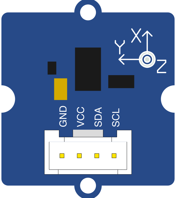
 Design with Seeed Grove 3-Axis Digital Accelerometer (±16g) in Cirkit Designer
Introduction
The Seeed Grove 3-Axis Digital Accelerometer (±16g) (Manufacturer Part ID: 101020054) is a compact and versatile sensor designed to measure acceleration in three dimensions: X, Y, and Z. With a measurement range of ±16g, this accelerometer is ideal for detecting motion, orientation, and vibration in a variety of applications. It is part of the Grove ecosystem, which simplifies prototyping and development with its plug-and-play modular design.
Explore Projects Built with Seeed Grove 3-Axis Digital Accelerometer (±16g)
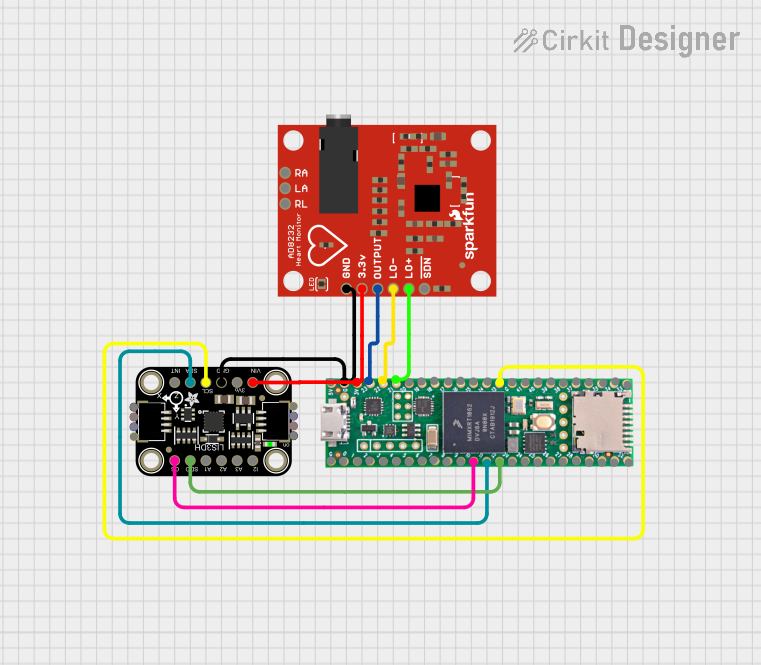 Open Project in Cirkit Designer
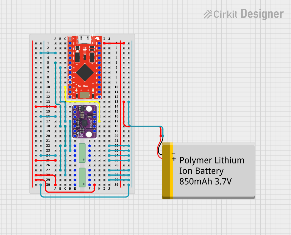 Open Project in Cirkit Designer
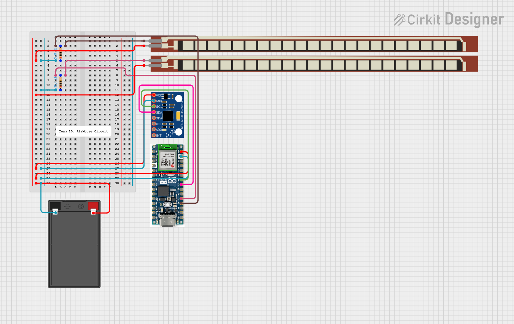 Open Project in Cirkit Designer
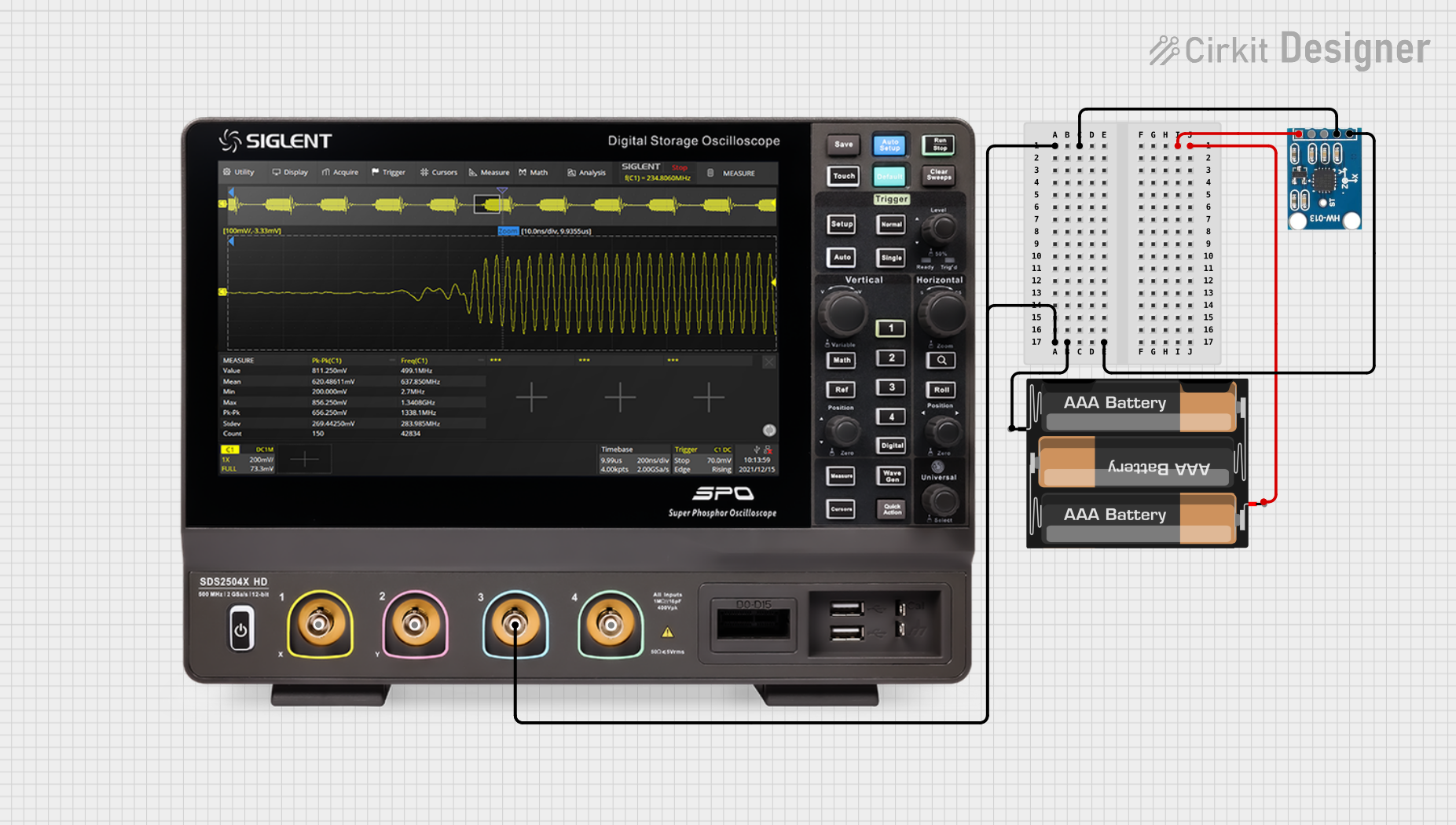 Open Project in Cirkit Designer
Explore Projects Built with Seeed Grove 3-Axis Digital Accelerometer (±16g)
Open Project in Cirkit DesignerOpen Project in Cirkit DesignerOpen Project in Cirkit DesignerOpen Project in Cirkit DesignerCommon Applications
- Motion detection and gesture recognition
- Orientation sensing for robotics and drones
- Vibration monitoring in industrial systems
- Wearable devices and fitness trackers
- Gaming and virtual reality controllers
Technical Specifications
The following table outlines the key technical details of the Seeed Grove 3-Axis Digital Accelerometer:
| Parameter | Value |
|---|---|
| Measurement Range | ±16g |
| Communication Protocol | I2C |
| Operating Voltage | 3.3V / 5V |
| Operating Current | < 1 mA |
| Sensitivity | 0.0039g/LSB (at ±16g range) |
| Dimensions | 20mm x 20mm |
| Operating Temperature | -40°C to +85°C |
Pin Configuration
The Grove connector on the accelerometer module has four pins. The table below describes each pin:
| Pin | Name | Description |
|---|---|---|
| 1 | VCC | Power supply (3.3V or 5V) |
| 2 | GND | Ground |
| 3 | SDA | I2C data line |
| 4 | SCL | I2C clock line |
Usage Instructions
Connecting the Accelerometer
Hardware Setup:
- Connect the Grove 3-Axis Digital Accelerometer to an I2C port on a Grove Base Shield or Grove-compatible board.
- If using an Arduino UNO, attach the Grove Base Shield to the Arduino UNO and connect the accelerometer to an available I2C port.
Software Setup:
- Install the required library for the accelerometer. The sensor is based on the LIS3DHTR chip, so you can use the
Seeed_LIS3DHTRlibrary. - Open the Arduino IDE and install the library via the Library Manager:
- Go to Sketch > Include Library > Manage Libraries.
- Search for
Seeed_LIS3DHTRand click Install.
- Install the required library for the accelerometer. The sensor is based on the LIS3DHTR chip, so you can use the
Sample Code
The following Arduino code demonstrates how to read acceleration data from the sensor:
#include <Wire.h>
#include "LIS3DHTR.h" // Include the library for the LIS3DHTR chip

LIS3DHTR<TwoWire> LIS; // Create an instance of the LIS3DHTR class

void setup() {
  Serial.begin(9600); // Initialize serial communication
  Wire.begin();       // Initialize I2C communication

  // Initialize the accelerometer
  if (!LIS.begin(Wire, 0x19)) { // Default I2C address is 0x19
    Serial.println("Failed to initialize accelerometer!");
    while (1); // Halt execution if initialization fails
  }

  LIS.setOutputDataRate(LIS3DHTR_DATARATE_50HZ); // Set data rate to 50Hz
  LIS.setFullScaleRange(LIS3DHTR_RANGE_16G);    // Set measurement range to ±16g
  Serial.println("Accelerometer initialized successfully!");
}

void loop() {
  // Read acceleration values for X, Y, and Z axes
  float x = LIS.getAccelerationX();
  float y = LIS.getAccelerationY();
  float z = LIS.getAccelerationZ();

  // Print the acceleration values to the Serial Monitor
  Serial.print("X: ");
  Serial.print(x, 2); // Print X-axis acceleration with 2 decimal places
  Serial.print(" g, Y: ");
  Serial.print(y, 2); // Print Y-axis acceleration with 2 decimal places
  Serial.print(" g, Z: ");
  Serial.print(z, 2); // Print Z-axis acceleration with 2 decimal places
  Serial.println(" g");

  delay(100); // Delay for 100ms before the next reading
}
Important Considerations
- Ensure the sensor is securely connected to the I2C port to avoid communication errors.
- The sensor operates at both 3.3V and 5V, but ensure your microcontroller's I2C lines are compatible with the chosen voltage.
- Avoid exposing the sensor to extreme temperatures or mechanical shocks beyond its specified limits.
Troubleshooting and FAQs
Common Issues
No Data Output:
- Ensure the Grove connector is properly seated in the I2C port.
- Verify that the correct I2C address (default: 0x19) is being used in the code.
Incorrect or Unstable Readings:
- Check for loose connections or damaged cables.
- Ensure the sensor is not exposed to excessive vibrations or noise during operation.
Library Not Found:
- Confirm that the
Seeed_LIS3DHTRlibrary is installed in the Arduino IDE. - Restart the Arduino IDE after installing the library.
- Confirm that the
FAQs
Q: Can I use this sensor with a Raspberry Pi?
A: Yes, the sensor supports I2C communication and can be used with a Raspberry Pi. You will need to configure the I2C interface on the Raspberry Pi and use a compatible Python library, such as smbus.
Q: What is the maximum sampling rate of the sensor?
A: The sensor supports a maximum output data rate of 5.3 kHz, but for most applications, lower rates (e.g., 50Hz or 100Hz) are sufficient.
Q: How do I change the measurement range?
A: Use the setFullScaleRange() function in the code to set the desired range. Supported ranges are ±2g, ±4g, ±8g, and ±16g.
Q: Can I use multiple accelerometers on the same I2C bus?
A: Yes, but you will need to configure each sensor with a unique I2C address. Refer to the sensor's datasheet for instructions on changing the address.
This concludes the documentation for the Seeed Grove 3-Axis Digital Accelerometer (±16g). For further assistance, refer to the official Seeed Studio documentation or community forums.