How to Use LED Red/Green: Examples, Pinouts, and Specs
Introduction
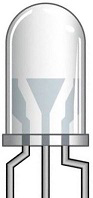
The Red/Green LED is a versatile light-emitting diode capable of emitting either red or green light, depending on the polarity of the applied voltage. This dual-color LED is commonly used in electronic circuits as an indicator, status light, or part of a display system. Its compact size, low power consumption, and ability to display two colors make it ideal for applications requiring simple visual feedback.
Explore Projects Built with LED Red/Green
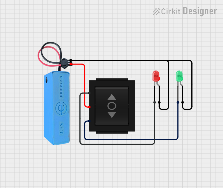
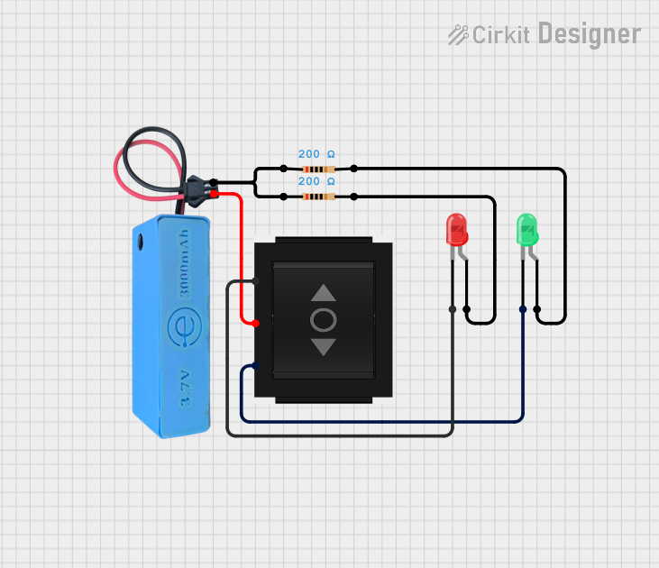
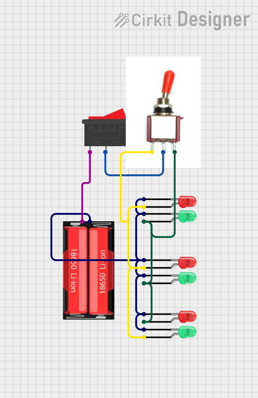

Explore Projects Built with LED Red/Green
Common Applications
- Power and status indicators
- Signal and error notifications
- Multi-state displays
- Educational and hobbyist projects
- Embedded systems and microcontroller-based circuits
Technical Specifications
Below are the key technical details for a typical Red/Green LED. Note that exact values may vary slightly depending on the manufacturer.
| Parameter | Value |
|---|---|
| Forward Voltage (Red) | 1.8V - 2.2V |
| Forward Voltage (Green) | 2.0V - 2.4V |
| Forward Current (typical) | 20mA |
| Maximum Current | 30mA |
| Reverse Voltage | 5V |
| Wavelength (Red) | 620nm - 630nm |
| Wavelength (Green) | 520nm - 530nm |
| Operating Temperature | -40°C to +85°C |
| Package Type | 3mm or 5mm (commonly used) |
Pin Configuration
The Red/Green LED typically has two pins, as shown in the table below:
| Pin | Description |
|---|---|
| Anode | Positive terminal for both red and green colors. |
| Cathode | Negative terminal. Polarity determines the color. |
Note: Some Red/Green LEDs may have three pins (common cathode or common anode). Refer to the specific datasheet for details.
Usage Instructions
How to Use the Red/Green LED in a Circuit
Determine the Polarity:
- For a two-pin Red/Green LED, the color depends on the direction of current flow:
- Forward bias (current flows from anode to cathode): Red light.
- Reverse bias (current flows from cathode to anode): Green light.
- For a three-pin LED, connect the common pin (anode or cathode) and control the other two pins to select the color.
- For a two-pin Red/Green LED, the color depends on the direction of current flow:
Use a Current-Limiting Resistor:
- Always connect a resistor in series with the LED to limit the current and prevent damage.
- Calculate the resistor value using Ohm's Law:
[ R = \frac{V_{supply} - V_{forward}}{I_{forward}} ] Example: For a 5V supply and a forward voltage of 2V (red), with a desired current of 20mA:
[ R = \frac{5V - 2V}{0.02A} = 150\Omega ]
Connect to a Microcontroller (e.g., Arduino UNO):
- Use a digital output pin to control the LED.
- Use two GPIO pins for a two-pin LED to toggle between red and green.
Example Arduino Code
The following code demonstrates how to control a two-pin Red/Green LED with an Arduino UNO:
// Define the pins connected to the LED
const int redPin = 9;  // Pin for red light (forward bias)
const int greenPin = 10; // Pin for green light (reverse bias)

void setup() {
  // Set the LED pins as outputs
  pinMode(redPin, OUTPUT);
  pinMode(greenPin, OUTPUT);
}

void loop() {
  // Turn on the red light
  digitalWrite(redPin, HIGH);
  digitalWrite(greenPin, LOW); // Ensure green is off
  delay(1000); // Keep red on for 1 second

  // Turn on the green light
  digitalWrite(redPin, LOW); // Ensure red is off
  digitalWrite(greenPin, HIGH);
  delay(1000); // Keep green on for 1 second
}
Important Considerations
- Polarity Matters: Incorrect polarity can prevent the LED from lighting up.
- Avoid Overcurrent: Exceeding the maximum current rating can permanently damage the LED.
- Use Proper Resistors: Always calculate and use the correct resistor value for your circuit.
Troubleshooting and FAQs
Common Issues
The LED Does Not Light Up:
- Check the polarity of the connections.
- Ensure the current-limiting resistor is not too large.
- Verify that the power supply voltage is sufficient.
The LED Is Dim:
- The resistor value may be too high, reducing the current.
- Check the supply voltage and ensure it meets the LED's forward voltage requirements.
The LED Flickers:
- This may occur if the power supply is unstable.
- Ensure proper connections and a stable voltage source.
The LED Only Lights Up in One Color:
- For a two-pin LED, verify that the polarity is being reversed correctly.
- For a three-pin LED, check the connections to the control pins.
FAQs
Q: Can I use the Red/Green LED without a resistor?
A: No, a resistor is essential to limit the current and prevent damage to the LED.
Q: How do I know which pin is the anode or cathode?
A: For a two-pin LED, the longer leg is typically the anode (positive). If the legs are trimmed, refer to the flat edge on the LED casing, which usually indicates the cathode.
Q: Can I control the LED with PWM?
A: Yes, you can use PWM (Pulse Width Modulation) to adjust the brightness of each color by controlling the duty cycle of the signal.
Q: What happens if I exceed the maximum current rating?
A: Exceeding the current rating can cause the LED to overheat and fail permanently.
By following this documentation, you can effectively use a Red/Green LED in your electronic projects!