How to Use GNSS: Examples, Pinouts, and Specs
Introduction
The Global Navigation Satellite System (GNSS) is a satellite-based navigation system that provides precise geolocation and time information to a GNSS receiver anywhere on Earth. It operates under all weather conditions, making it a reliable solution for a wide range of applications. GNSS is widely used in navigation, mapping, surveying, autonomous vehicles, agriculture, and timing synchronization for telecommunications and power grids.
Common applications and use cases include:
- Vehicle navigation systems
- Geospatial mapping and surveying
- Precision agriculture
- Autonomous drones and robotics
- Timing synchronization for critical infrastructure
Explore Projects Built with GNSS


Explore Projects Built with GNSS
Technical Specifications
Below are the key technical details and pin configuration for a typical GNSS module:
Key Technical Details
| Parameter | Specification |
|---|---|
| Operating Voltage | 3.3V to 5V |
| Current Consumption | 20mA to 50mA (varies by module) |
| Positioning Accuracy | Typically 2.5m CEP (Circular Error Probable) |
| Time to First Fix (TTFF) | Cold Start: ~30s, Hot Start: ~1s |
| Communication Interface | UART, I2C, or SPI |
| Frequency Bands | L1 (1575.42 MHz), L2, L5 (varies by system) |
| Supported Systems | GPS, GLONASS, Galileo, BeiDou, QZSS |
Pin Configuration and Descriptions
| Pin Name | Pin Number | Description |
|---|---|---|
| VCC | 1 | Power supply input (3.3V to 5V) |
| GND | 2 | Ground connection |
| TX | 3 | UART Transmit pin (data output) |
| RX | 4 | UART Receive pin (data input) |
| PPS | 5 | Pulse Per Second output for timing |
| EN | 6 | Enable pin (active high) |
| SDA | 7 | I2C Data line (optional, module-specific) |
| SCL | 8 | I2C Clock line (optional, module-specific) |
Note: Pin configuration may vary depending on the specific GNSS module. Always refer to the datasheet of your module for exact details.
Usage Instructions
How to Use the GNSS Module in a Circuit
- Power Supply: Connect the
VCCpin to a 3.3V or 5V power source, depending on the module's requirements. Connect theGNDpin to the ground of your circuit. - Data Communication: Use the
TXandRXpins for UART communication. ConnectTXto the RX pin of your microcontroller andRXto the TX pin of your microcontroller. - Optional Connections: If your module supports I2C, connect the
SDAandSCLpins to the corresponding pins on your microcontroller. Use pull-up resistors (typically 4.7kΩ) on these lines. - Antenna: Attach an external GNSS antenna to the module's antenna port for better signal reception.
- Enable Pin: If the module has an
ENpin, ensure it is pulled high to enable the module.
Important Considerations and Best Practices
- Antenna Placement: Place the antenna in an open area with a clear view of the sky for optimal satellite reception.
- Power Supply: Use a stable and noise-free power supply to avoid interference with GNSS signals.
- Baud Rate: Configure the UART baud rate of the GNSS module to match your microcontroller's settings (commonly 9600 bps).
- Signal Interference: Avoid placing the module near high-frequency components or metal enclosures that can block signals.
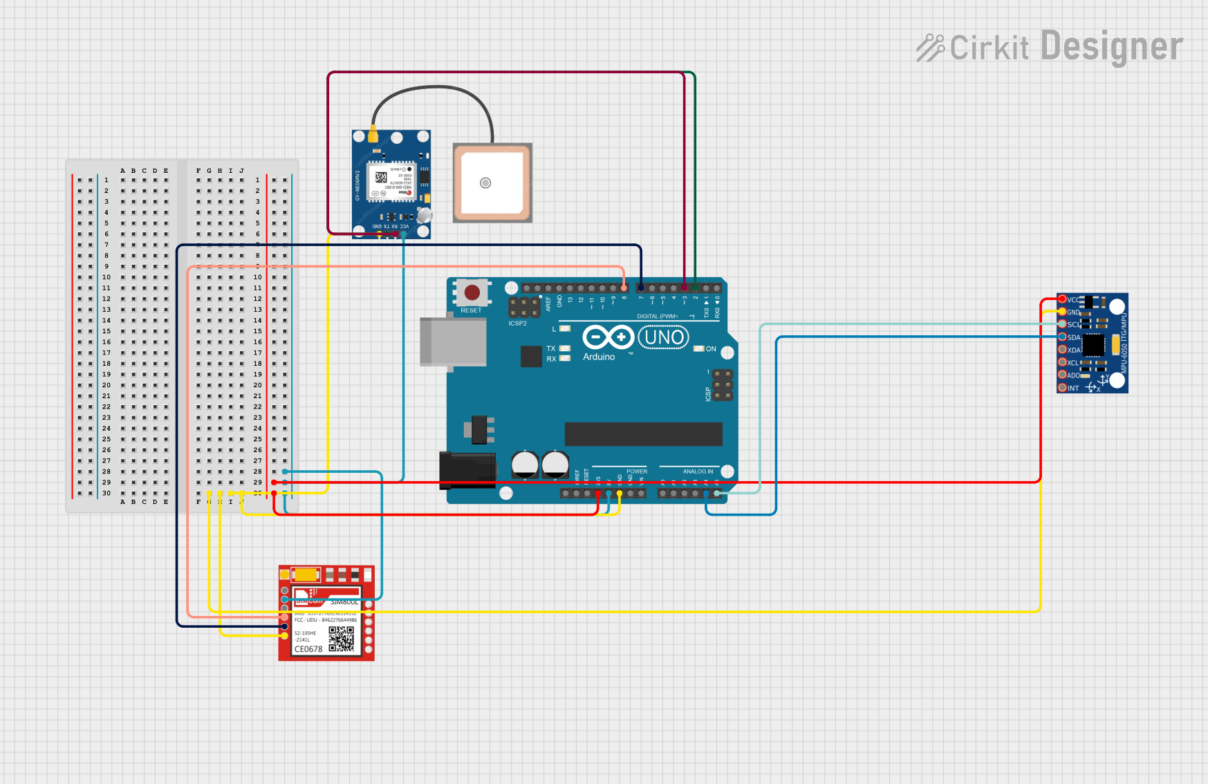
Example: Connecting GNSS to Arduino UNO
Below is an example of how to interface a GNSS module with an Arduino UNO using UART communication:
Circuit Connections
| GNSS Pin | Arduino Pin |
|---|---|
| VCC | 5V |
| GND | GND |
| TX | Pin 4 |
| RX | Pin 3 |
Arduino Code
#include <SoftwareSerial.h>

// Define RX and TX pins for SoftwareSerial
SoftwareSerial GNSS(3, 4); // RX = Pin 3, TX = Pin 4

void setup() {
  Serial.begin(9600); // Initialize Serial Monitor at 9600 bps
  GNSS.begin(9600);   // Initialize GNSS module at 9600 bps

  Serial.println("GNSS Module Initialized");
}

void loop() {
  // Check if data is available from the GNSS module
  if (GNSS.available()) {
    // Read data from GNSS and send it to Serial Monitor
    while (GNSS.available()) {
      char c = GNSS.read();
      Serial.print(c);
    }
  }
}
Note: The above code reads raw NMEA sentences from the GNSS module and outputs them to the Serial Monitor. You can use libraries like TinyGPS++ to parse and extract specific data such as latitude, longitude, and time.
Troubleshooting and FAQs
Common Issues and Solutions
No Data Output from GNSS Module
- Cause: Incorrect wiring or baud rate mismatch.
- Solution: Double-check the connections and ensure the UART baud rate matches the module's default setting.
Poor Signal Reception
- Cause: Antenna placement or environmental obstructions.
- Solution: Place the antenna in an open area with a clear view of the sky. Avoid indoor use or areas with tall buildings.
Module Not Powering On
- Cause: Insufficient power supply or incorrect voltage.
- Solution: Verify the power supply voltage and current requirements. Ensure proper connections to
VCCandGND.
Intermittent Data Loss
- Cause: Electrical noise or interference.
- Solution: Use decoupling capacitors near the power pins and keep the module away from high-frequency components.
FAQs
Q: Can I use the GNSS module indoors?
A: GNSS modules generally require a clear view of the sky for accurate positioning. Indoor use may result in poor or no signal reception.
Q: What is the difference between GPS and GNSS?
A: GPS is a specific satellite navigation system operated by the United States, while GNSS refers to a broader term encompassing multiple systems like GPS, GLONASS, Galileo, and BeiDou.
Q: How do I parse NMEA sentences from the GNSS module?
A: You can use libraries like TinyGPS++ or Adafruit GPS to parse NMEA sentences and extract useful data such as latitude, longitude, and time.
Q: What is the purpose of the PPS pin?
A: The Pulse Per Second (PPS) pin provides a precise timing signal that can be used for synchronization in time-sensitive applications.
By following this documentation, you can effectively integrate and troubleshoot a GNSS module in your projects.