How to Use Anemometr: Examples, Pinouts, and Specs
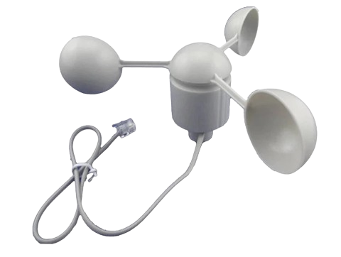
Anemometer (Manufacturer: China, Part ID: Anemometr)
Introduction
The Anemometer is a device designed to measure wind speed and direction. It is widely used in meteorology, aviation, environmental monitoring, and renewable energy systems such as wind turbines. This component is essential for applications requiring accurate wind data, including weather stations, agricultural monitoring, and HVAC systems.
The Anemometr model is a versatile and reliable sensor that can be easily integrated into various electronic systems, including microcontroller platforms like Arduino. Its robust design ensures accurate measurements even in harsh environmental conditions.
Technical Specifications
The following table outlines the key technical details of the Anemometr:
| Parameter | Value |
|---|---|
| Operating Voltage | 5V DC |
| Operating Current | ≤ 20 mA |
| Output Signal | Pulse signal (frequency-based) |
| Wind Speed Range | 0.3 m/s to 30 m/s |
| Accuracy | ±3% |
| Operating Temperature | -30°C to 70°C |
| Connector Type | 3-pin (VCC, GND, Signal) |
| Material | ABS plastic (weather-resistant) |
| Dimensions | 120mm x 120mm x 150mm |
| Weight | 200g |
Pin Configuration
The Anemometr has a 3-pin connector. The pinout is described in the table below:
| Pin | Name | Description |
|---|---|---|
| 1 | VCC | Power supply input (5V DC) |
| 2 | GND | Ground connection |
| 3 | Signal | Pulse output signal proportional to wind speed |
Usage Instructions
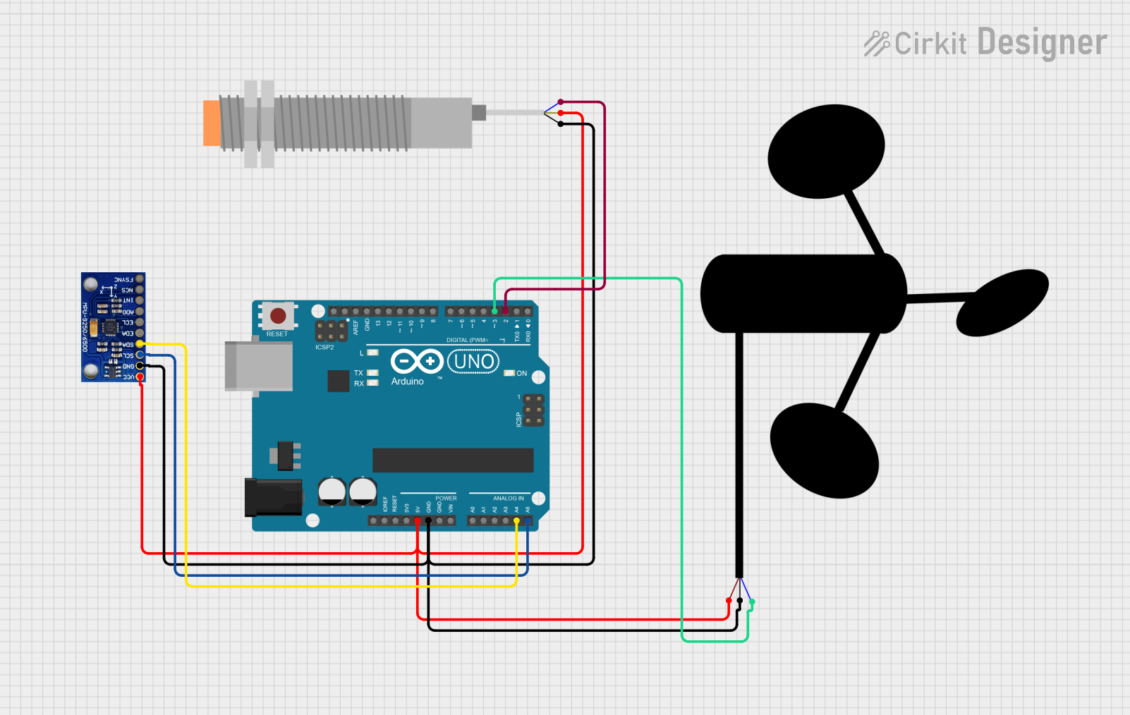
Connecting the Anemometer to a Circuit
- Power Supply: Connect the VCC pin to a 5V DC power source and the GND pin to the ground of your circuit.
- Signal Output: Connect the Signal pin to a digital input pin on your microcontroller (e.g., Arduino). A pull-up resistor (10kΩ) may be required for stable signal readings.
- Wind Speed Calculation: The anemometer outputs a pulse signal where the frequency is proportional to the wind speed. The relationship between frequency and wind speed is typically provided in the datasheet or calibration chart.
Arduino Example Code
Below is an example of how to interface the Anemometr with an Arduino UNO to measure wind speed:
// Anemometer Example Code
// Measures wind speed using the Anemometr sensor
// Manufacturer: China, Part ID: Anemometr

const int signalPin = 2;  // Digital pin connected to the Signal pin of the anemometer
volatile int pulseCount = 0;  // Variable to store pulse count
unsigned long lastMillis = 0; // Timer for calculating wind speed

// Wind speed calculation constants
const float windSpeedFactor = 2.4; // Factor to convert pulses to m/s (example value)

void setup() {
  pinMode(signalPin, INPUT_PULLUP); // Set signal pin as input with pull-up resistor
  attachInterrupt(digitalPinToInterrupt(signalPin), countPulse, FALLING);
  Serial.begin(9600); // Initialize serial communication
}

void loop() {
  unsigned long currentMillis = millis();

  // Calculate wind speed every second
  if (currentMillis - lastMillis >= 1000) {
    detachInterrupt(digitalPinToInterrupt(signalPin)); // Disable interrupt temporarily
    float windSpeed = (pulseCount / windSpeedFactor); // Calculate wind speed in m/s
    pulseCount = 0; // Reset pulse count
    lastMillis = currentMillis; // Update timer
    attachInterrupt(digitalPinToInterrupt(signalPin), countPulse, FALLING); // Re-enable interrupt

    // Print wind speed to the serial monitor
    Serial.print("Wind Speed: ");
    Serial.print(windSpeed);
    Serial.println(" m/s");
  }
}

// Interrupt service routine to count pulses
void countPulse() {
  pulseCount++;
}
Important Considerations
- Calibration: Ensure the anemometer is calibrated for accurate wind speed measurements. Refer to the manufacturer’s calibration chart for the pulse-to-speed conversion factor.
- Placement: Install the anemometer in an open area, free from obstructions, to avoid inaccurate readings caused by turbulence.
- Weatherproofing: The Anemometr is weather-resistant, but ensure proper sealing of electrical connections to prevent water ingress.
Troubleshooting and FAQs
Common Issues
No Signal Output
- Cause: Loose or incorrect wiring.
- Solution: Verify all connections. Ensure the VCC and GND pins are properly connected to the power supply.
Inaccurate Wind Speed Readings
- Cause: Incorrect calibration or placement.
- Solution: Check the calibration factor and ensure the anemometer is installed in an open area.
Intermittent Signal
- Cause: Electrical noise or insufficient pull-up resistor.
- Solution: Add a 10kΩ pull-up resistor to the signal line and ensure proper grounding.
Arduino Not Detecting Pulses
- Cause: Interrupt not configured correctly.
- Solution: Verify the interrupt pin configuration in the code and ensure the signal pin is connected to a valid interrupt pin.
FAQs
Q1: Can the anemometer measure wind direction?
A1: No, the Anemometr model measures only wind speed. For wind direction, a separate wind vane sensor is required.
Q2: What is the maximum cable length for the anemometer?
A2: The maximum cable length depends on the signal integrity and power supply. For best results, use shielded cables and keep the length under 10 meters.
Q3: Can I use the anemometer with a 3.3V microcontroller?
A3: The Anemometr requires a 5V power supply. Use a level shifter or voltage divider to interface the signal pin with a 3.3V microcontroller.
Conclusion
The Anemometr is a reliable and easy-to-use anemometer for measuring wind speed in various applications. Its compatibility with microcontrollers like Arduino makes it an excellent choice for hobbyists and professionals alike. By following the usage instructions and best practices outlined in this documentation, you can achieve accurate and consistent wind speed measurements.
Explore Projects Built with Anemometr
Explore Projects Built with Anemometr