How to Use GT-U7: Examples, Pinouts, and Specs
Introduction
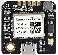
The GT-U7 is a GPS module manufactured by Goouuu Tech, designed to provide accurate location and time data. It is equipped with a high-sensitivity GPS receiver, making it suitable for a wide range of applications. The module is compact, lightweight, and easy to integrate with microcontrollers, making it a popular choice for navigation systems, robotics, and tracking devices. Its compatibility with UART communication ensures seamless integration with platforms like Arduino, Raspberry Pi, and other microcontroller-based systems.
Explore Projects Built with GT-U7
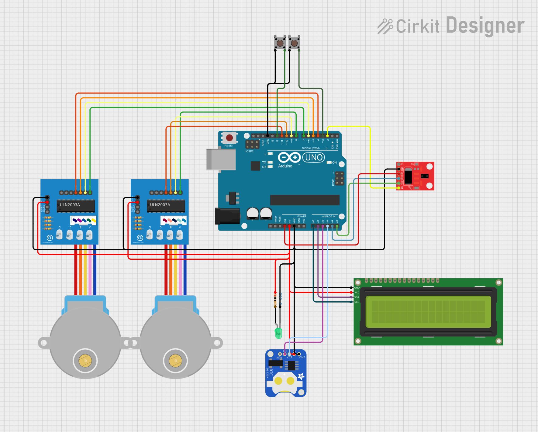
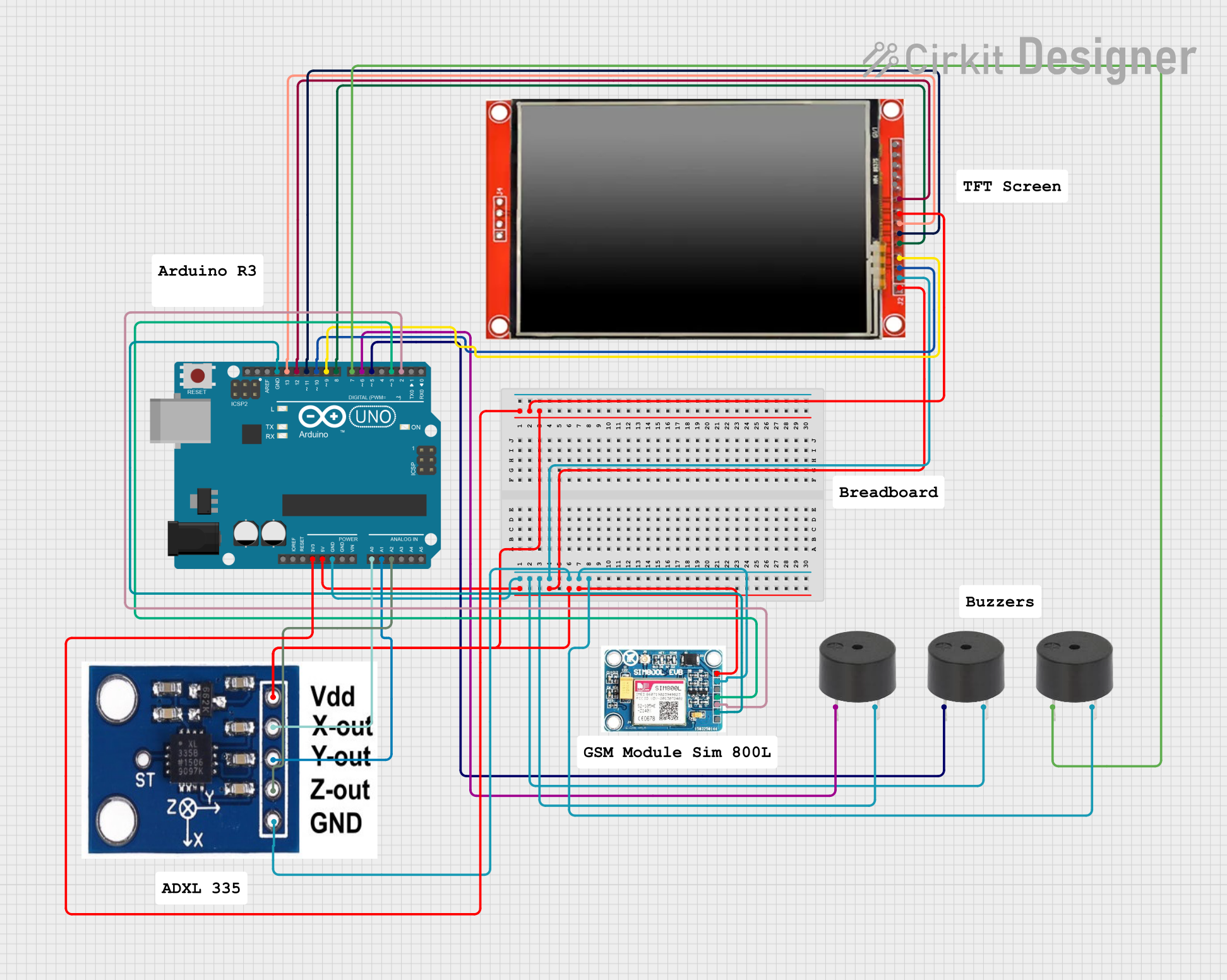

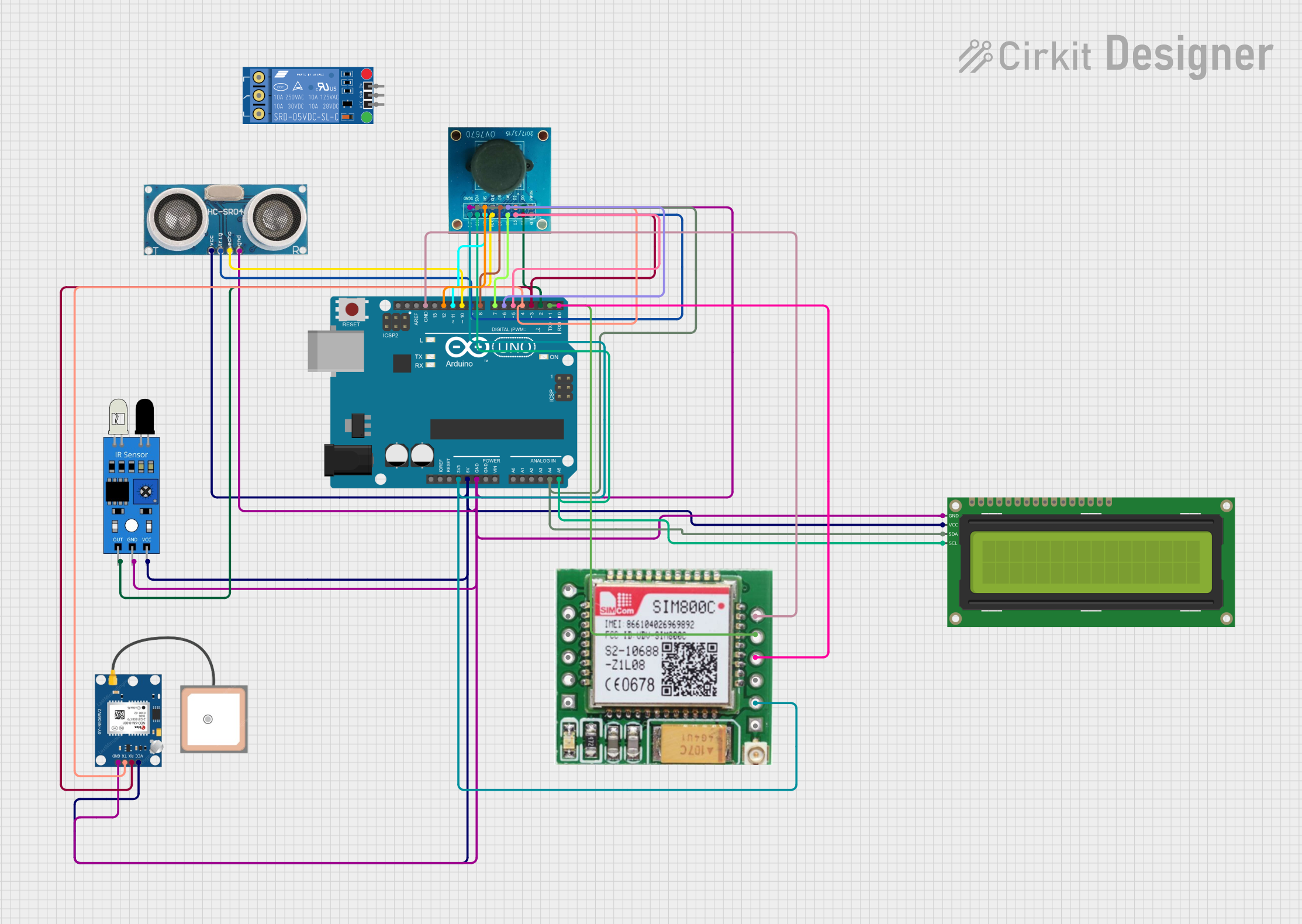
Explore Projects Built with GT-U7
Common Applications
- Navigation systems for vehicles and drones
- Robotics requiring precise location data
- Asset and personal tracking devices
- Time synchronization for IoT systems
- Geographic data logging
Technical Specifications
The GT-U7 GPS module is designed to deliver reliable performance with the following key specifications:
| Parameter | Specification |
|---|---|
| Manufacturer | Goouuu Tech |
| Part ID | GT-U7 |
| Input Voltage | 3.3V to 5.0V |
| Communication Interface | UART (default baud rate: 9600 bps) |
| GPS Chipset | U-Blox NEO-7 |
| Position Accuracy | 2.5 meters (CEP) |
| Time Accuracy | 30 ns |
| Cold Start Time | 27 seconds |
| Hot Start Time | 1 second |
| Operating Temperature | -40°C to +85°C |
| Dimensions | 25mm x 35mm x 6mm |
| Antenna | External active antenna (included) |
Pin Configuration
The GT-U7 module has a simple pinout for easy integration. Below is the pin configuration:
| Pin | Name | Description |
|---|---|---|
| 1 | VCC | Power input (3.3V to 5.0V) |
| 2 | GND | Ground connection |
| 3 | TXD | UART Transmit pin (connect to RX of microcontroller) |
| 4 | RXD | UART Receive pin (connect to TX of microcontroller) |
| 5 | PPS | Pulse Per Second output (used for precise timing applications, optional) |
Usage Instructions
Connecting the GT-U7 to a Microcontroller
To use the GT-U7 GPS module, follow these steps:
- Power the Module: Connect the VCC pin to a 3.3V or 5.0V power source and the GND pin to ground.
- Establish UART Communication: Connect the TXD pin of the GT-U7 to the RX pin of your microcontroller, and the RXD pin of the GT-U7 to the TX pin of your microcontroller.
- Antenna Placement: Attach the included active antenna to the module and ensure it has a clear view of the sky for optimal GPS signal reception.
- Configure Baud Rate: The default baud rate is 9600 bps. Ensure your microcontroller's UART settings match this value.
Example: Using GT-U7 with Arduino UNO
Below is an example of how to use the GT-U7 module with an Arduino UNO to read GPS data:
#include <SoftwareSerial.h>

// Define RX and TX pins for SoftwareSerial
SoftwareSerial gpsSerial(4, 3); // RX = Pin 4, TX = Pin 3

void setup() {
  Serial.begin(9600);          // Initialize Serial Monitor at 9600 bps
  gpsSerial.begin(9600);       // Initialize GPS module at 9600 bps
  Serial.println("GT-U7 GPS Module Test");
}

void loop() {
  // Check if data is available from the GPS module
  while (gpsSerial.available()) {
    char c = gpsSerial.read(); // Read one character from GPS module
    Serial.print(c);           // Print the character to Serial Monitor
  }
}
Best Practices
- Antenna Placement: Place the antenna in an open area with minimal obstructions for better signal reception.
- Power Supply: Use a stable power source to avoid fluctuations that may affect GPS performance.
- UART Settings: Ensure the baud rate and UART settings match between the GT-U7 and your microcontroller.
- Signal Acquisition: Allow the module a few seconds to acquire satellite signals, especially during a cold start.
Troubleshooting and FAQs
Common Issues and Solutions
No GPS Data Output
- Cause: Incorrect wiring or baud rate mismatch.
- Solution: Double-check the connections and ensure the baud rate is set to 9600 bps.
Poor Signal Reception
- Cause: Antenna is obstructed or placed indoors.
- Solution: Move the antenna to an open area with a clear view of the sky.
Module Not Powering On
- Cause: Insufficient power supply.
- Solution: Verify that the VCC pin is receiving 3.3V to 5.0V and the GND pin is properly connected.
Data Appears as Gibberish
- Cause: Baud rate mismatch between the module and microcontroller.
- Solution: Ensure both devices are set to the same baud rate (default: 9600 bps).
FAQs
Q: Can the GT-U7 work indoors?
A: While the GT-U7 can function indoors, signal reception may be weak or unavailable. For best results, use the module outdoors with a clear view of the sky.
Q: How many satellites does the GT-U7 need for accurate positioning?
A: The GT-U7 requires a minimum of 4 satellites for accurate 3D positioning.
Q: Can I change the default baud rate?
A: Yes, the baud rate can be changed using specific configuration commands sent to the module. Refer to the U-Blox NEO-7 documentation for details.
Q: What is the purpose of the PPS pin?
A: The PPS (Pulse Per Second) pin provides a precise timing signal that can be used for synchronization in time-sensitive applications.
By following this documentation, you can effectively integrate and utilize the GT-U7 GPS module in your projects.