Cirkit Designer Logo
Cirkit Designer
Your all-in-one circuit design IDE
Home / 
Component Documentation

How to Use Adafruit 8x16 LED Matrix FeatherWing - Blue: Examples, Pinouts, and Specs

Image of Adafruit 8x16 LED Matrix FeatherWing - Blue
Cirkit Designer LogoDesign with Adafruit 8x16 LED Matrix FeatherWing - Blue in Cirkit Designer

Introduction

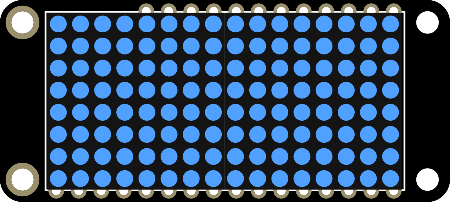
The Adafruit 8x16 LED Matrix FeatherWing - Blue is a versatile and compact display module that adds a bright, eye-catching LED array to your projects. With 128 individual blue LEDs arranged in an 8x16 grid, it is perfect for displaying simple graphics, scrolling text, and animations. This component is designed to interface seamlessly with the Adafruit Feather series of development boards, making it an excellent choice for portable and IoT applications.

Explore Projects Built with Adafruit 8x16 LED Matrix FeatherWing - Blue

Use Cirkit Designer to design, explore, and prototype these projects online. Some projects support real-time simulation. Click "Open Project" to start designing instantly!
Arduino-Controlled RGB LED Matrix Display
Image of SMD2121 Led screen: A project utilizing Adafruit 8x16 LED Matrix FeatherWing - Blue in a practical application
This circuit connects an Arduino UNO R4 WiFi microcontroller to a 64x32 LED matrix display. The Arduino is configured to control the LED matrix, sending color data and control signals to display various colors across the matrix. The embedded code on the Arduino cycles through a range of colors, filling the entire LED matrix with each color in sequence.
Cirkit Designer LogoOpen Project in Cirkit Designer
Arduino UNO WiFi-Controlled LED Matrix Display
Image of SMD2121 Led screen - r4: A project utilizing Adafruit 8x16 LED Matrix FeatherWing - Blue in a practical application
This circuit consists of an Arduino UNO R4 WiFi microcontroller connected to a 64x32 LED matrix. The Arduino controls the LED matrix by sending signals to various pins to display different colors and patterns, as defined in the embedded code.
Cirkit Designer LogoOpen Project in Cirkit Designer
Arduino-Controlled Dual WS2812 RGB LED Matrix Eye Animation Display
Image of eye project: A project utilizing Adafruit 8x16 LED Matrix FeatherWing - Blue in a practical application
This circuit consists of an Arduino UNO microcontroller connected to two daisy-chained WS2812 RGB LED 8x8 matrices. The Arduino controls the LED matrices to display patterns that simulate a slow blinking human eyes effect. The code for the Arduino is written to create and cycle through different eye patterns, varying from open to half-closed to closed, to achieve the blinking effect.
Cirkit Designer LogoOpen Project in Cirkit Designer
ESP32-Controlled WS2812 LED Matrix Display with Resistor
Image of esp32 door sign project: A project utilizing Adafruit 8x16 LED Matrix FeatherWing - Blue in a practical application
This circuit features an ESP32 microcontroller connected to a 32x8 WS2812 LED matrix. The ESP32 controls the LED matrix through a 220-ohm resistor connected to its D12 pin, providing data input to the matrix, while power and ground connections are shared between the ESP32 and the LED matrix.
Cirkit Designer LogoOpen Project in Cirkit Designer

Explore Projects Built with Adafruit 8x16 LED Matrix FeatherWing - Blue

Use Cirkit Designer to design, explore, and prototype these projects online. Some projects support real-time simulation. Click "Open Project" to start designing instantly!
Image of SMD2121 Led screen: A project utilizing Adafruit 8x16 LED Matrix FeatherWing - Blue in a practical application
Arduino-Controlled RGB LED Matrix Display
This circuit connects an Arduino UNO R4 WiFi microcontroller to a 64x32 LED matrix display. The Arduino is configured to control the LED matrix, sending color data and control signals to display various colors across the matrix. The embedded code on the Arduino cycles through a range of colors, filling the entire LED matrix with each color in sequence.
Cirkit Designer LogoOpen Project in Cirkit Designer
Image of SMD2121 Led screen - r4: A project utilizing Adafruit 8x16 LED Matrix FeatherWing - Blue in a practical application
Arduino UNO WiFi-Controlled LED Matrix Display
This circuit consists of an Arduino UNO R4 WiFi microcontroller connected to a 64x32 LED matrix. The Arduino controls the LED matrix by sending signals to various pins to display different colors and patterns, as defined in the embedded code.
Cirkit Designer LogoOpen Project in Cirkit Designer
Image of eye project: A project utilizing Adafruit 8x16 LED Matrix FeatherWing - Blue in a practical application
Arduino-Controlled Dual WS2812 RGB LED Matrix Eye Animation Display
This circuit consists of an Arduino UNO microcontroller connected to two daisy-chained WS2812 RGB LED 8x8 matrices. The Arduino controls the LED matrices to display patterns that simulate a slow blinking human eyes effect. The code for the Arduino is written to create and cycle through different eye patterns, varying from open to half-closed to closed, to achieve the blinking effect.
Cirkit Designer LogoOpen Project in Cirkit Designer
Image of esp32 door sign project: A project utilizing Adafruit 8x16 LED Matrix FeatherWing - Blue in a practical application
ESP32-Controlled WS2812 LED Matrix Display with Resistor
This circuit features an ESP32 microcontroller connected to a 32x8 WS2812 LED matrix. The ESP32 controls the LED matrix through a 220-ohm resistor connected to its D12 pin, providing data input to the matrix, while power and ground connections are shared between the ESP32 and the LED matrix.
Cirkit Designer LogoOpen Project in Cirkit Designer

Common Applications and Use Cases

  • Wearable electronics
  • Informational displays
  • Portable message boards
  • Interactive art installations
  • User interfaces for projects

Technical Specifications

Key Technical Details

  • Operating Voltage: 3.3V to 5V
  • Max Current (per LED): 18mA
  • Max Current (for all LEDs): ~2.3A
  • Communication Interface: I2C
  • I2C Addresses: 0x70 (default), selectable with solder jumpers
  • Dimensions: 51mm x 23mm x 4.6mm

Pin Configuration and Descriptions

Pin Description
GND Ground connection
3V 3.3V power supply
SDA I2C Data
SCL I2C Clock
RST Reset pin (optional use)

Usage Instructions

How to Use the Component in a Circuit

  1. Power Supply: Connect the 3V pin to the 3.3V output on your Feather board and GND to ground.
  2. I2C Connection: Connect SDA and SCL pins to their corresponding I2C pins on the Feather.
  3. Optional Reset: The RST pin can be connected to a digital pin on the Feather if software reset functionality is desired.

Important Considerations and Best Practices

  • Ensure that the power supply is sufficient for the maximum current draw when all LEDs are lit.
  • Use pull-up resistors on the I2C lines if they are not included on the Feather board.
  • To prevent damage, avoid powering the LEDs at their maximum current for extended periods.
  • When stacking multiple FeatherWings, ensure that the I2C addresses are set uniquely using the solder jumpers.

Example Code for Arduino UNO

#include <Wire.h>
#include <Adafruit_GFX.h>
#include <Adafruit_LEDBackpack.h>

Adafruit_8x16matrix matrix = Adafruit_8x16matrix();

void setup() {
  matrix.begin(0x70); // Initialize the matrix with its I2C address
  matrix.setBrightness(10); // Set brightness level (0 is dim, 15 is bright)
}

void loop() {
  matrix.clear(); // Clear the matrix display
  matrix.setCursor(0, 0); // Set cursor at top-left corner
  matrix.print("Hello"); // Print a message
  matrix.writeDisplay(); // Update the display with the message
  delay(2000); // Wait for 2 seconds
  matrix.scrollTextLeft(); // Scroll the text left
  matrix.writeDisplay(); // Update the display after scrolling
  delay(300); // Wait for 300 milliseconds
}

Note: This example assumes the use of an Adafruit Feather or a compatible board with the same I2C pinout. If using an Arduino UNO, you will need to connect SDA to A4 and SCL to A5, and include a level shifter if necessary due to the voltage difference.

Troubleshooting and FAQs

Common Issues

  • LEDs Not Lighting Up: Check the power connections and ensure the I2C lines are properly connected.
  • Dim or Flickering LEDs: Verify that the power supply can handle the current draw. Adjust the brightness level if necessary.
  • Garbled Display: Ensure that there are no conflicting I2C addresses if using multiple I2C devices.

Solutions and Tips for Troubleshooting

  • Double-check wiring, especially the I2C connections.
  • Use a multimeter to verify that the correct voltage is present at the 3V pin.
  • If using multiple FeatherWings, change the I2C address of each one using the solder jumpers.
  • Check for loose connections or cold solder joints if the module is not functioning correctly.

FAQs

Q: Can I use this LED matrix with other microcontrollers besides the Feather series?

A: Yes, the matrix uses I2C, which is a standard communication protocol. However, you may need level shifters for microcontrollers operating at different voltages.

Q: How do I change the I2C address?

A: The I2C address can be changed by soldering the address jumpers on the back of the PCB. Refer to the Adafruit documentation for the address mapping.

Q: Can I power the matrix from a battery?

A: Yes, as long as the battery can provide the necessary voltage and current. Be mindful of the power consumption when all LEDs are lit.

Q: How do I display custom graphics or animations?

A: Custom graphics and animations can be created using the Adafruit GFX library functions. You will need to define the patterns as bitmaps or use drawing functions provided by the library.