Cirkit Designer Logo
Cirkit Designer
Your all-in-one circuit design IDE
Home / 
Component Documentation

How to Use tb6600 Micro Stepping Motor Driver: Examples, Pinouts, and Specs

Image of tb6600 Micro Stepping Motor Driver
Cirkit Designer LogoDesign with tb6600 Micro Stepping Motor Driver in Cirkit Designer

Introduction

The TB6600 Micro Stepping Motor Driver is a professional-grade driver module designed to control stepper motors with precision and efficiency. Manufactured by DFROBOT, this driver is capable of powering a wide range of stepper motors, making it suitable for applications such as CNC machines, 3D printers, and robotics. Its ability to micro-step allows for smoother and quieter motor operation, as well as increased accuracy in motion control.

Explore Projects Built with tb6600 Micro Stepping Motor Driver

Use Cirkit Designer to design, explore, and prototype these projects online. Some projects support real-time simulation. Click "Open Project" to start designing instantly!
CNC Machine Control System with Dual tb6600 Stepper Drivers and MAch3 USB Interface
Image of Jayshree CNC: A project utilizing tb6600 Micro Stepping Motor Driver in a practical application
This circuit appears to be a control system for a CNC machine or similar automated equipment. It includes two tb6600 Micro Stepping Motor Drivers for controlling stepper motors, a DC power source with a step-down buck converter to provide the necessary voltage levels, and a 4-channel relay module for switching higher power loads. The MAch3 CNC USB interface suggests the system is designed to interface with computer numerical control software, and the RMCS_3001 BLDC Driver indicates the presence of a brushless DC motor control. The Tiva C launchpad microcontroller and various connectors imply that the system is modular and may be programmable for specific automation tasks.
Cirkit Designer LogoOpen Project in Cirkit Designer
Stepper Motor Control System with TB6600 Driver and DKC-1A Controller
Image of Copy of Copy of PLC-Based Step Motor Speed and Direction Control System: A project utilizing tb6600 Micro Stepping Motor Driver in a practical application
This circuit controls a bipolar stepper motor using a tb6600 micro stepping motor driver and a DKC-1A stepper motor controller. The system is powered by a 24VDC power supply and includes a relay module for additional control functionalities.
Cirkit Designer LogoOpen Project in Cirkit Designer
Stepper Motor Control System with TB6600 Driver and Relay Integration
Image of Copy of Copy of Copy of PLC-Based Step Motor Speed and Direction Control System: A project utilizing tb6600 Micro Stepping Motor Driver in a practical application
This circuit controls a bipolar stepper motor using a tb6600 micro stepping motor driver and a DKC-1A stepper motor controller. It includes a 24VDC power supply, a 4-channel relay module, and panel mount banana sockets for power connections. The motor driver and controller are interconnected to manage the motor's direction and pulse signals.
Cirkit Designer LogoOpen Project in Cirkit Designer
ESP32 and TB6600/TB660 Stepper Motor Driver Joystick-Controlled Dual Stepper Motor System
Image of esp32_dual steppermotor: A project utilizing tb6600 Micro Stepping Motor Driver in a practical application
This circuit controls two NEMA23 stepper motors using TB6600 and TB660 stepper motor drivers, interfaced with an ESP32 microcontroller. The ESP32 reads inputs from a KY-023 Dual Axis Joystick Module to control the direction and movement of the motors, with power supplied by a 12V power source and regulated by a Step Up Boost Power Converter.
Cirkit Designer LogoOpen Project in Cirkit Designer

Explore Projects Built with tb6600 Micro Stepping Motor Driver

Use Cirkit Designer to design, explore, and prototype these projects online. Some projects support real-time simulation. Click "Open Project" to start designing instantly!
Image of Jayshree CNC: A project utilizing tb6600 Micro Stepping Motor Driver in a practical application
CNC Machine Control System with Dual tb6600 Stepper Drivers and MAch3 USB Interface
This circuit appears to be a control system for a CNC machine or similar automated equipment. It includes two tb6600 Micro Stepping Motor Drivers for controlling stepper motors, a DC power source with a step-down buck converter to provide the necessary voltage levels, and a 4-channel relay module for switching higher power loads. The MAch3 CNC USB interface suggests the system is designed to interface with computer numerical control software, and the RMCS_3001 BLDC Driver indicates the presence of a brushless DC motor control. The Tiva C launchpad microcontroller and various connectors imply that the system is modular and may be programmable for specific automation tasks.
Cirkit Designer LogoOpen Project in Cirkit Designer
Image of Copy of Copy of PLC-Based Step Motor Speed and Direction Control System: A project utilizing tb6600 Micro Stepping Motor Driver in a practical application
Stepper Motor Control System with TB6600 Driver and DKC-1A Controller
This circuit controls a bipolar stepper motor using a tb6600 micro stepping motor driver and a DKC-1A stepper motor controller. The system is powered by a 24VDC power supply and includes a relay module for additional control functionalities.
Cirkit Designer LogoOpen Project in Cirkit Designer
Image of Copy of Copy of Copy of PLC-Based Step Motor Speed and Direction Control System: A project utilizing tb6600 Micro Stepping Motor Driver in a practical application
Stepper Motor Control System with TB6600 Driver and Relay Integration
This circuit controls a bipolar stepper motor using a tb6600 micro stepping motor driver and a DKC-1A stepper motor controller. It includes a 24VDC power supply, a 4-channel relay module, and panel mount banana sockets for power connections. The motor driver and controller are interconnected to manage the motor's direction and pulse signals.
Cirkit Designer LogoOpen Project in Cirkit Designer
Image of esp32_dual steppermotor: A project utilizing tb6600 Micro Stepping Motor Driver in a practical application
ESP32 and TB6600/TB660 Stepper Motor Driver Joystick-Controlled Dual Stepper Motor System
This circuit controls two NEMA23 stepper motors using TB6600 and TB660 stepper motor drivers, interfaced with an ESP32 microcontroller. The ESP32 reads inputs from a KY-023 Dual Axis Joystick Module to control the direction and movement of the motors, with power supplied by a 12V power source and regulated by a Step Up Boost Power Converter.
Cirkit Designer LogoOpen Project in Cirkit Designer

Common Applications and Use Cases

  • CNC milling machines and lathes
  • 3D printers
  • Robotic arms and actuators
  • Precision XY tables
  • Automated equipment and assembly lines

Technical Specifications

Key Technical Details

  • Input Voltage: 9V-42V DC
  • Output Current: Adjustable from 0.2A to 4.0A
  • Control Signal Voltage: 3.3V-24V
  • Microstepping: Up to 1/32 micro steps
  • Operating Temperature: -10°C to 45°C

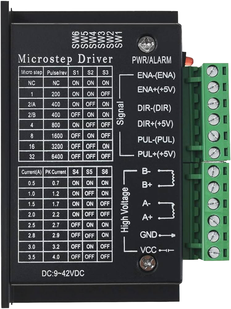
Pin Configuration and Descriptions

Pin Number Pin Name Description
1 ENA+ Enable signal positive
2 ENA- Enable signal negative
3 DIR+ Direction signal positive
4 DIR- Direction signal negative
5 PUL+ Pulse signal positive
6 PUL- Pulse signal negative
7 VCC Motor power supply positive
8 GND Motor power supply negative

Usage Instructions

How to Use the Component in a Circuit

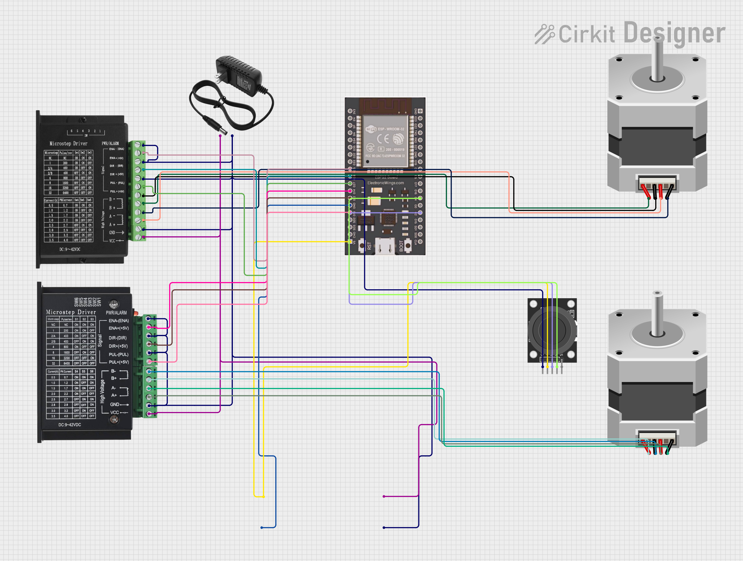
  1. Power Supply Connection: Connect a DC power supply to the VCC and GND pins, ensuring that the voltage is within the specified range (9V-42V).

  2. Motor Connection: Connect the stepper motor wires to the motor output terminals on the TB6600 driver, observing the correct wiring sequence as per the motor's datasheet.

  3. Control Signal Connection: Connect the ENA+, DIR+, and PUL+ pins to the corresponding output pins on your controller (e.g., Arduino UNO). Connect the ENA-, DIR-, and PUL- to the ground of the controller.

  4. Microstep Configuration: Set the microstep resolution using the onboard DIP switches according to the desired step size.

  5. Current Setting: Adjust the current setting using the onboard potentiometer to match the requirements of the stepper motor.

Important Considerations and Best Practices

  • Always ensure the power supply is turned off before making any connections to prevent damage.
  • Use a suitable heatsink to dissipate heat during operation.
  • Avoid running the motor driver at its maximum current rating for extended periods to prevent overheating.
  • Ensure that the control signals from the microcontroller are within the acceptable voltage range.

Example Code for Arduino UNO

// Define the stepper motor control pins
#define ENA 8
#define DIR 9
#define PUL 10

void setup() {
  // Set the control pins as outputs
  pinMode(ENA, OUTPUT);
  pinMode(DIR, OUTPUT);
  pinMode(PUL, OUTPUT);

  // Enable the stepper motor driver
  digitalWrite(ENA, LOW);
}

void loop() {
  // Set the direction of the motor
  digitalWrite(DIR, HIGH); // Set to LOW to change direction

  // Pulse the PUL pin to move the motor
  digitalWrite(PUL, HIGH);
  delayMicroseconds(500); // Adjust the speed by changing the delay
  digitalWrite(PUL, LOW);
  delayMicroseconds(500);
}

Troubleshooting and FAQs

Common Issues Users Might Face

  • Motor not moving: Check power supply connections, ensure the motor driver is enabled, and verify that the control signals are being sent correctly.
  • Motor stalling or vibrating: Adjust the current setting, check for proper microstep configuration, and ensure the motor is not overloaded.
  • Overheating: Ensure adequate cooling, reduce the operating current, or check for short circuits.

Solutions and Tips for Troubleshooting

  • Double-check all connections and ensure they are secure and correct.
  • Use a multimeter to verify the voltage levels at the power supply and the control signals.
  • Consult the stepper motor's datasheet to ensure compatibility with the driver settings.

FAQs

Q: Can I use the TB6600 driver with a 5V control signal? A: Yes, the TB6600 can accept control signal voltages from 3.3V to 24V.

Q: What is the maximum motor current that the TB6600 can handle? A: The TB6600 can handle up to 4.0A of output current with proper cooling.

Q: How do I set the microstepping resolution? A: Use the onboard DIP switches to select the desired microstepping resolution according to the driver's manual.

Q: Can I run two motors simultaneously with one TB6600 driver? A: No, the TB6600 is designed to control a single stepper motor. Each motor requires its own driver.

Remember to always refer to the manufacturer's datasheet and manual for the most accurate and detailed information about the TB6600 Micro Stepping Motor Driver.