Cirkit Designer Logo
Cirkit Designer
Your all-in-one circuit design IDE
Home / 
Component Documentation

How to Use ESP-WROOM-32: Examples, Pinouts, and Specs

Image of ESP-WROOM-32
Cirkit Designer LogoDesign with ESP-WROOM-32 in Cirkit Designer

Introduction

The ESP-WROOM-32 is a powerful Wi-Fi and Bluetooth module based on the ESP32 chip. It is designed for Internet of Things (IoT) applications, offering dual-core processing, low power consumption, and a wide range of GPIO options. This module is highly versatile and can be used in projects requiring wireless communication, sensor integration, or edge computing.

Explore Projects Built with ESP-WROOM-32

Use Cirkit Designer to design, explore, and prototype these projects online. Some projects support real-time simulation. Click "Open Project" to start designing instantly!
ESP32-Based Multi-Sensor Health Monitoring System with Bluetooth Connectivity
Image of circuit diagram: A project utilizing ESP-WROOM-32 in a practical application
This circuit features an ESP32-WROOM-32UE microcontroller as the central processing unit, interfacing with a variety of sensors and modules. It includes a MAX30100 pulse oximeter and heart-rate sensor, an MLX90614 infrared thermometer, an HC-05 Bluetooth module for wireless communication, and a Neo 6M GPS module for location tracking. All components are powered by a common voltage supply and are connected to specific GPIO pins on the ESP32 for data exchange, with the sensors using I2C communication and the modules using UART.
Cirkit Designer LogoOpen Project in Cirkit Designer
ESP32-Based GPS Tracker with SD Card Logging and Barometric Sensor
Image of gps projekt circuit: A project utilizing ESP-WROOM-32 in a practical application
This circuit features an ESP32 Wroom Dev Kit as the main microcontroller, interfaced with an MPL3115A2 sensor for pressure and temperature readings, and a Neo 6M GPS module for location tracking. The ESP32 is also connected to an SD card reader for data logging purposes. A voltage regulator is used to step down the USB power supply to 3.3V, which powers the ESP32, the sensor, and the SD card reader.
Cirkit Designer LogoOpen Project in Cirkit Designer
ESP32 and NRF24L01 Wireless Control Circuit
Image of master Node: A project utilizing ESP-WROOM-32 in a practical application
This circuit features an ESP32-WROOM-32UE microcontroller interfaced with an NRF24L01 wireless transceiver module, allowing for wireless communication capabilities. A pushbutton with a pull-down resistor is connected to the ESP32 for user input. Power regulation is managed by an AMS1117 3.3V regulator, which receives 5V from an AC-DC PSU board and is stabilized by an electrolytic capacitor, providing a stable 3.3V supply to the ESP32 and NRF24L01.
Cirkit Designer LogoOpen Project in Cirkit Designer
ESP32-Based Infrared Proximity Sensing System
Image of ir sensor: A project utilizing ESP-WROOM-32 in a practical application
This circuit features an ESP32 Wroom microcontroller connected to an Infrared Proximity Sensor. The ESP32's GPIO33 is interfaced with the sensor's output, allowing the microcontroller to read proximity data. The sensor is powered by the ESP32's 5V output, and both devices share a common ground.
Cirkit Designer LogoOpen Project in Cirkit Designer

Explore Projects Built with ESP-WROOM-32

Use Cirkit Designer to design, explore, and prototype these projects online. Some projects support real-time simulation. Click "Open Project" to start designing instantly!
Image of circuit diagram: A project utilizing ESP-WROOM-32 in a practical application
ESP32-Based Multi-Sensor Health Monitoring System with Bluetooth Connectivity
This circuit features an ESP32-WROOM-32UE microcontroller as the central processing unit, interfacing with a variety of sensors and modules. It includes a MAX30100 pulse oximeter and heart-rate sensor, an MLX90614 infrared thermometer, an HC-05 Bluetooth module for wireless communication, and a Neo 6M GPS module for location tracking. All components are powered by a common voltage supply and are connected to specific GPIO pins on the ESP32 for data exchange, with the sensors using I2C communication and the modules using UART.
Cirkit Designer LogoOpen Project in Cirkit Designer
Image of gps projekt circuit: A project utilizing ESP-WROOM-32 in a practical application
ESP32-Based GPS Tracker with SD Card Logging and Barometric Sensor
This circuit features an ESP32 Wroom Dev Kit as the main microcontroller, interfaced with an MPL3115A2 sensor for pressure and temperature readings, and a Neo 6M GPS module for location tracking. The ESP32 is also connected to an SD card reader for data logging purposes. A voltage regulator is used to step down the USB power supply to 3.3V, which powers the ESP32, the sensor, and the SD card reader.
Cirkit Designer LogoOpen Project in Cirkit Designer
Image of master Node: A project utilizing ESP-WROOM-32 in a practical application
ESP32 and NRF24L01 Wireless Control Circuit
This circuit features an ESP32-WROOM-32UE microcontroller interfaced with an NRF24L01 wireless transceiver module, allowing for wireless communication capabilities. A pushbutton with a pull-down resistor is connected to the ESP32 for user input. Power regulation is managed by an AMS1117 3.3V regulator, which receives 5V from an AC-DC PSU board and is stabilized by an electrolytic capacitor, providing a stable 3.3V supply to the ESP32 and NRF24L01.
Cirkit Designer LogoOpen Project in Cirkit Designer
Image of ir sensor: A project utilizing ESP-WROOM-32 in a practical application
ESP32-Based Infrared Proximity Sensing System
This circuit features an ESP32 Wroom microcontroller connected to an Infrared Proximity Sensor. The ESP32's GPIO33 is interfaced with the sensor's output, allowing the microcontroller to read proximity data. The sensor is powered by the ESP32's 5V output, and both devices share a common ground.
Cirkit Designer LogoOpen Project in Cirkit Designer

Common Applications and Use Cases

  • Smart home devices (e.g., smart lights, thermostats)
  • Wearable technology
  • Industrial IoT systems
  • Wireless sensor networks
  • Robotics and automation
  • Prototyping and development of connected devices

Technical Specifications

The ESP-WROOM-32 module is built around the ESP32-D0WDQ6 chip, which integrates Wi-Fi and Bluetooth capabilities. Below are the key technical details:

General Specifications

Parameter Value
Microcontroller ESP32-D0WDQ6
Wireless Connectivity Wi-Fi 802.11 b/g/n, Bluetooth v4.2 BR/EDR
CPU Dual-core Xtensa® 32-bit LX6
Clock Speed Up to 240 MHz
Flash Memory 4 MB (default)
SRAM 520 KB
Operating Voltage 3.0V to 3.6V
Power Consumption Ultra-low power modes available
Operating Temperature -40°C to 85°C

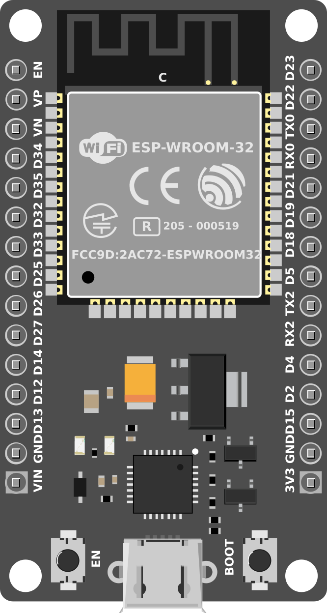
Pin Configuration and Descriptions

The ESP-WROOM-32 module has 38 pins. Below is a table of the most commonly used pins:

Pin Number Pin Name Functionality
1 EN Enable pin (active high)
2 IO0 GPIO0, used for boot mode selection
3 IO2 GPIO2, general-purpose I/O
4 IO4 GPIO4, general-purpose I/O
5 IO5 GPIO5, general-purpose I/O
6 IO12 GPIO12, ADC2 channel 5
7 IO13 GPIO13, ADC2 channel 4
8 IO14 GPIO14, ADC2 channel 6
9 IO15 GPIO15, ADC2 channel 3
10 IO16 GPIO16, general-purpose I/O
11 IO17 GPIO17, general-purpose I/O
12 GND Ground
13 3V3 3.3V power supply

Note: Some GPIO pins have specific functions or limitations. For example, GPIO0 is used for boot mode selection, and certain pins are input-only or have pull-up/down resistors.
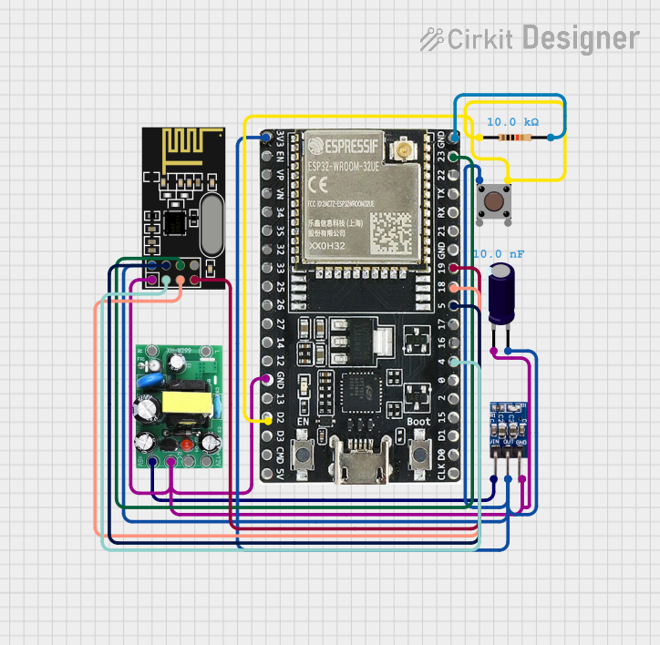
Usage Instructions

How to Use the ESP-WROOM-32 in a Circuit

  1. Power Supply: Connect the module to a stable 3.3V power source. Avoid exceeding 3.6V to prevent damage.
  2. Boot Mode: To upload code, connect GPIO0 to GND and reset the module. After uploading, disconnect GPIO0 from GND.
  3. Programming: Use the UART interface (TX/RX pins) to program the module via a USB-to-serial adapter or development board.
  4. GPIO Usage: Connect sensors, actuators, or other peripherals to the GPIO pins. Refer to the pin configuration table for details.

Important Considerations and Best Practices

  • Voltage Levels: Ensure all connected peripherals operate at 3.3V logic levels. Use level shifters if necessary.
  • Power Supply: Use a decoupling capacitor (e.g., 10 µF) near the power pins to stabilize the voltage.
  • Antenna Placement: Avoid placing metal objects near the module's antenna to ensure optimal wireless performance.
  • Deep Sleep Mode: Use the deep sleep mode to reduce power consumption in battery-powered applications.

Example Code for Arduino UNO

The ESP-WROOM-32 can be programmed using the Arduino IDE. Below is an example of how to connect the module to a Wi-Fi network:

#include <WiFi.h> // Include the Wi-Fi library for ESP32

const char* ssid = "Your_SSID";       // Replace with your Wi-Fi network name
const char* password = "Your_Password"; // Replace with your Wi-Fi password

void setup() {
  Serial.begin(115200); // Initialize serial communication at 115200 baud
  delay(1000);          // Wait for a moment to stabilize

  Serial.println("Connecting to Wi-Fi...");
  WiFi.begin(ssid, password); // Start connecting to the Wi-Fi network

  while (WiFi.status() != WL_CONNECTED) {
    delay(500); // Wait for connection
    Serial.print(".");
  }

  Serial.println("\nConnected to Wi-Fi!");
  Serial.print("IP Address: ");
  Serial.println(WiFi.localIP()); // Print the assigned IP address
}

void loop() {
  // Add your main code here
}

Note: Replace Your_SSID and Your_Password with your Wi-Fi credentials.

Troubleshooting and FAQs

Common Issues and Solutions

  1. Module Not Responding

    • Cause: Incorrect power supply or wiring.
    • Solution: Ensure the module is powered with 3.3V and all connections are secure.
  2. Wi-Fi Connection Fails

    • Cause: Incorrect SSID or password.
    • Solution: Double-check the Wi-Fi credentials in your code.
  3. Upload Fails

    • Cause: GPIO0 not connected to GND during boot mode.
    • Solution: Connect GPIO0 to GND, reset the module, and try uploading again.
  4. Random Resets

    • Cause: Insufficient power supply or unstable voltage.
    • Solution: Use a stable 3.3V power source and add decoupling capacitors.

FAQs

  • Q: Can the ESP-WROOM-32 operate on 5V?
    A: No, the module operates at 3.3V. Use a voltage regulator or level shifter for 5V systems.

  • Q: How do I reset the module?
    A: Pull the EN pin low momentarily to reset the module.

  • Q: Can I use the ESP-WROOM-32 with Bluetooth and Wi-Fi simultaneously?
    A: Yes, the ESP32 chip supports simultaneous use of Wi-Fi and Bluetooth.

  • Q: What is the maximum range of the Wi-Fi connection?
    A: The range depends on environmental factors but typically extends up to 100 meters in open space.

This documentation provides a comprehensive guide to using the ESP-WROOM-32 module effectively in your projects.