How to Use Push Button Round: Examples, Pinouts, and Specs
Introduction
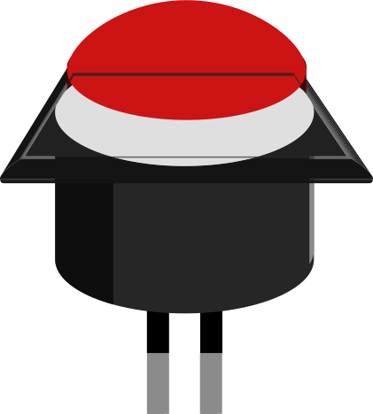
- The Push Button Round is a momentary switch that allows users to make or break a circuit by pressing it. When pressed, the button completes the circuit, and when released, it returns to its default open state.
- Commonly used in electronic devices for user input, such as power buttons, reset switches, and control panels. It is also widely used in DIY electronics projects, prototyping, and embedded systems.
Explore Projects Built with Push Button Round
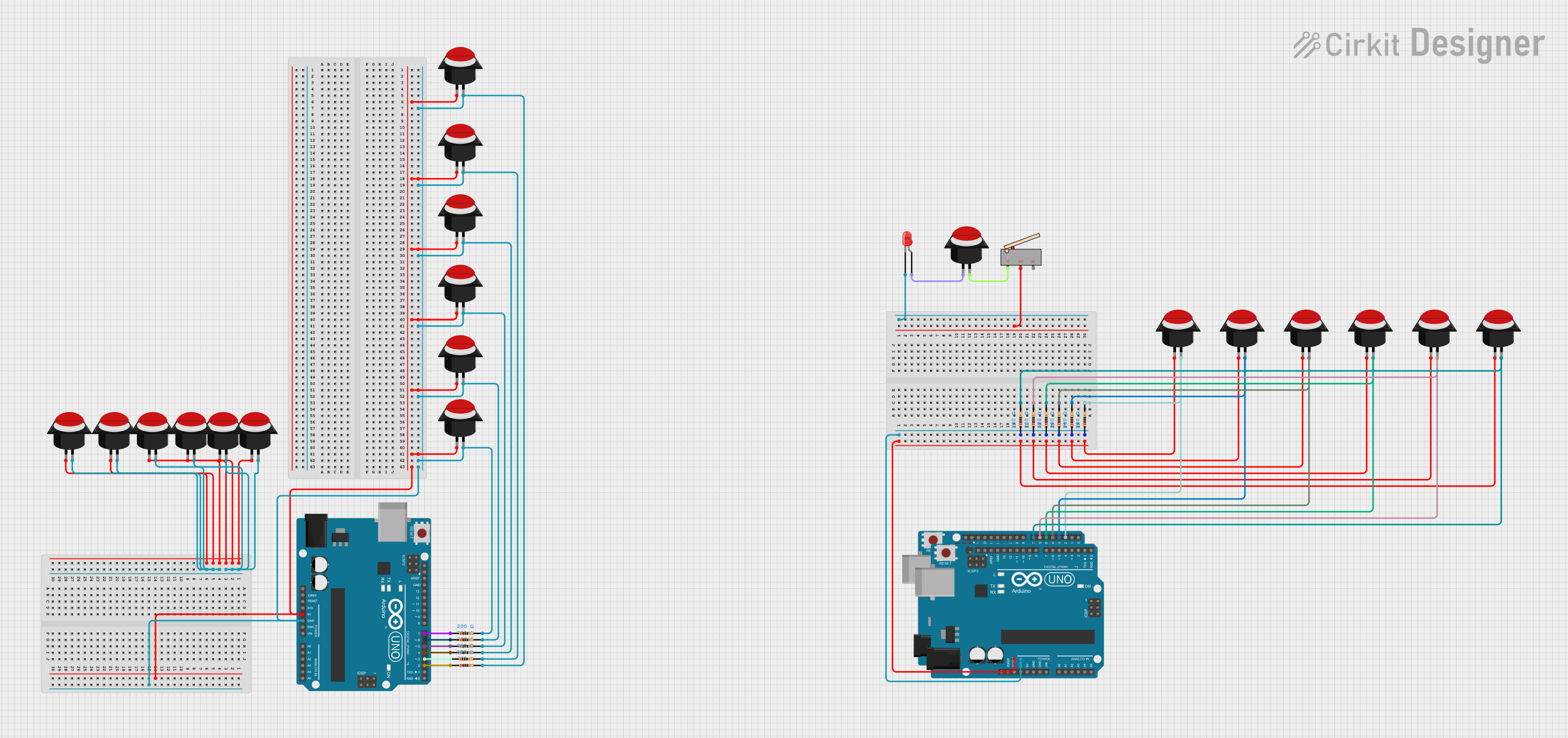

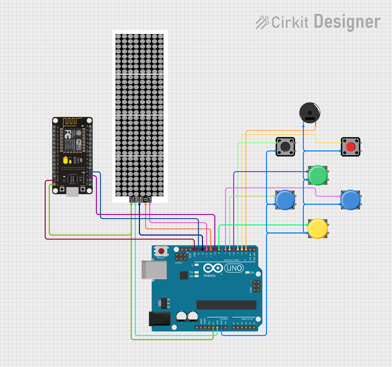

Explore Projects Built with Push Button Round
Technical Specifications
- Type: Momentary push button (normally open)
- Shape: Round
- Material: Plastic or metal housing with conductive contacts
- Voltage Rating: Typically 3V to 24V (check specific model for exact rating)
- Current Rating: Typically 50mA to 500mA
- Contact Resistance: ≤ 50mΩ
- Insulation Resistance: ≥ 100MΩ at 500V DC
- Operating Temperature: -20°C to +70°C
- Mounting Type: Panel mount or PCB mount
- Actuation Force: Typically 150g to 300g
Pin Configuration and Descriptions
The Push Button Round typically has two or four pins, depending on the model. Below is a description of the pin configuration:
For 2-Pin Push Button:
| Pin Number | Description |
|---|---|
| 1 | Terminal 1 (connect to circuit) |
| 2 | Terminal 2 (connect to circuit) |
For 4-Pin Push Button:
| Pin Number | Description |
|---|---|
| 1 | Terminal 1 (connect to circuit) |
| 2 | Terminal 2 (connect to circuit) |
| 3 | Terminal 3 (internally connected to Terminal 1) |
| 4 | Terminal 4 (internally connected to Terminal 2) |
Note: For 4-pin buttons, terminals 1 and 3 are internally connected, as are terminals 2 and 4. This ensures flexibility in PCB design.
Usage Instructions
How to Use the Push Button Round in a Circuit
- Identify the Terminals: For a 2-pin button, connect one terminal to the input signal and the other to ground. For a 4-pin button, use any pair of internally connected terminals.
- Connect to a Microcontroller: If using with a microcontroller (e.g., Arduino UNO), connect one terminal to a digital input pin and the other to ground. Use a pull-up or pull-down resistor to ensure stable operation.
- Debounce the Button: Push buttons can produce noise or "bouncing" when pressed. Use hardware (capacitor) or software (debouncing code) to eliminate this effect.
Important Considerations and Best Practices
- Voltage and Current Ratings: Ensure the button's voltage and current ratings match your circuit requirements to avoid damage.
- Debouncing: Always implement debouncing to prevent erratic behavior in your circuit.
- Mounting: Securely mount the button to prevent accidental disconnection or damage.
- Resistor Usage: Use a pull-up or pull-down resistor (typically 10kΩ) to stabilize the input signal.
Example: Connecting to an Arduino UNO
Below is an example of how to connect and use a Push Button Round with an Arduino UNO:
Circuit Diagram
- Connect one terminal of the button to digital pin 2 on the Arduino.
- Connect the other terminal to ground.
- Use the Arduino's internal pull-up resistor to simplify the circuit.
Code Example
// Push Button Example with Arduino UNO
// This code reads the state of a push button and turns on an LED when pressed.

const int buttonPin = 2;  // Pin connected to the push button
const int ledPin = 13;    // Pin connected to the onboard LED

void setup() {
  pinMode(buttonPin, INPUT_PULLUP); // Set button pin as input with internal pull-up
  pinMode(ledPin, OUTPUT);          // Set LED pin as output
}

void loop() {
  int buttonState = digitalRead(buttonPin); // Read the button state

  if (buttonState == LOW) { // Button pressed (LOW due to pull-up resistor)
    digitalWrite(ledPin, HIGH); // Turn on the LED
  } else {
    digitalWrite(ledPin, LOW);  // Turn off the LED
  }
}
Note: The internal pull-up resistor ensures the button pin is HIGH when the button is not pressed, avoiding floating input issues.
Troubleshooting and FAQs
Common Issues
Button Not Responding:
- Check the wiring and ensure the button is properly connected.
- Verify that the button's voltage and current ratings match your circuit.
- Test the button with a multimeter to confirm it is functioning.
Erratic Behavior (Button Bouncing):
- Implement hardware debouncing using a capacitor (e.g., 0.1µF) across the button terminals.
- Use software debouncing in your microcontroller code.
Button Stuck or Difficult to Press:
- Inspect for physical damage or debris around the button.
- Ensure the button is securely mounted and not over-tightened.
FAQs
Q1: Can I use the Push Button Round with a 5V circuit?
A1: Yes, most Push Button Round models support 5V operation. Check the specific voltage rating of your button to confirm.
Q2: Do I need an external pull-up resistor if using an Arduino?
A2: No, the Arduino has an internal pull-up resistor that can be enabled in the code (INPUT_PULLUP).
Q3: How do I debounce the button in software?
A3: Use a delay or a state-checking algorithm in your code to filter out noise caused by button bouncing.
Q4: Can I use the button for high-power applications?
A4: No, Push Button Round switches are designed for low-power applications. Use a relay or transistor for high-power circuits.
By following this documentation, you can effectively integrate the Push Button Round into your electronic projects!