How to Use AS5600 Magnetic Encoder: Examples, Pinouts, and Specs
Introduction
The AS5600 is a contactless magnetic rotary position sensor designed for precise angle measurement. It operates by detecting the position of a rotating magnet placed above the sensor, providing high-resolution 12-bit angle data. The AS5600 is highly versatile, featuring an I2C interface for seamless integration into digital systems and an analog output for broader compatibility. Its compact design and robust performance make it ideal for applications requiring accurate position sensing without physical contact.
Explore Projects Built with AS5600 Magnetic Encoder


Explore Projects Built with AS5600 Magnetic Encoder
Common Applications and Use Cases
- Robotics: Joint position sensing and motor control
- Industrial automation: Rotary encoders for machinery
- Consumer electronics: Knob position detection
- Automotive: Steering angle and throttle position sensing
- Medical devices: Precision control systems
Technical Specifications
The AS5600 offers a range of features that make it suitable for various applications. Below are its key technical details:
Key Technical Details
| Parameter | Value |
|---|---|
| Supply Voltage (VDD) | 3.0V to 3.6V |
| Operating Current | 6.5 mA (typical) |
| Resolution | 12-bit (4096 positions) |
| Interface | I2C and Analog Output |
| Magnetic Field Strength | 20 mT to 80 mT |
| Operating Temperature | -40°C to +125°C |
| Maximum Output Frequency | 1 kHz |
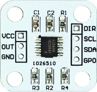
Pin Configuration and Descriptions
The AS5600 is typically available in an 8-pin SOIC package. Below is the pinout and description:
| Pin Number | Pin Name | Description |
|---|---|---|
| 1 | OUT | Analog output for angle position (PWM or voltage, depending on configuration) |
| 2 | VDD | Positive supply voltage (3.0V to 3.6V) |
| 3 | GND | Ground connection |
| 4 | SDA | I2C data line |
| 5 | SCL | I2C clock line |
| 6 | DIR | Direction input (sets clockwise or counterclockwise rotation) |
| 7 | PWM | Configurable as PWM output or external clock input |
| 8 | NC | Not connected (leave floating) |
Usage Instructions
The AS5600 is straightforward to use in a circuit, whether for analog or digital applications. Below are the steps and considerations for integrating the AS5600 into your project.
How to Use the AS5600 in a Circuit
- Power Supply: Connect the VDD pin to a 3.3V power source and the GND pin to ground.
- Magnet Placement: Place a diametrically magnetized magnet (e.g., a neodymium magnet) above the AS5600 sensor. Ensure the magnetic field strength is within the 20 mT to 80 mT range.
- I2C Communication:
- Connect the SDA and SCL pins to the corresponding I2C pins on your microcontroller.
- Use pull-up resistors (typically 4.7 kΩ) on the SDA and SCL lines.
- Analog Output: If using the analog output, connect the OUT pin to an ADC input on your microcontroller.
- Direction Control: Use the DIR pin to set the rotation direction. Connect it to VDD for clockwise or GND for counterclockwise.
Important Considerations and Best Practices
- Magnet Alignment: Ensure the magnet is centered above the AS5600 for accurate readings.
- Magnetic Field Strength: Use a magnet with the recommended field strength to avoid measurement errors.
- I2C Address: The default I2C address of the AS5600 is
0x36. Ensure no other devices on the I2C bus share this address. - Filtering: For noisy environments, consider adding capacitors to the power supply lines to reduce noise.
Example Code for Arduino UNO
Below is an example of how to interface the AS5600 with an Arduino UNO using the I2C interface:
#include <Wire.h>

// AS5600 I2C address
#define AS5600_ADDR 0x36

// Register addresses
#define RAW_ANGLE_HIGH 0x0C
#define RAW_ANGLE_LOW  0x0D

void setup() {
  Wire.begin(); // Initialize I2C communication
  Serial.begin(9600); // Start serial communication for debugging
}

void loop() {
  uint16_t rawAngle = readRawAngle(); // Read the raw angle value
  float angle = (rawAngle * 360.0) / 4096.0; // Convert to degrees (12-bit resolution)

  Serial.print("Angle: ");
  Serial.print(angle);
  Serial.println(" degrees");

  delay(500); // Wait for 500ms before the next reading
}

// Function to read the raw angle from the AS5600
uint16_t readRawAngle() {
  Wire.beginTransmission(AS5600_ADDR);
  Wire.write(RAW_ANGLE_HIGH); // Request the high byte of the raw angle
  Wire.endTransmission(false); // Send repeated start condition
  Wire.requestFrom(AS5600_ADDR, 2); // Request 2 bytes (high and low)

  uint8_t highByte = Wire.read(); // Read the high byte
  uint8_t lowByte = Wire.read();  // Read the low byte

  return (highByte << 8) | lowByte; // Combine high and low bytes into a 16-bit value
}
Troubleshooting and FAQs
Common Issues and Solutions
No Output or Incorrect Readings:
- Cause: Magnet not aligned properly.
- Solution: Ensure the magnet is centered above the sensor and within the specified distance.
I2C Communication Fails:
- Cause: Incorrect wiring or missing pull-up resistors.
- Solution: Verify the SDA and SCL connections and add 4.7 kΩ pull-up resistors if needed.
Analog Output Not Working:
- Cause: Incorrect configuration or wiring.
- Solution: Check the OUT pin connection and ensure the sensor is configured for analog output.
Inconsistent Measurements:
- Cause: Magnetic interference or noise.
- Solution: Use a shielded enclosure or move the sensor away from other magnetic sources.
FAQs
Q: Can the AS5600 measure linear motion?
A: No, the AS5600 is designed for rotary position sensing and requires a rotating magnet.
Q: What type of magnet should I use?
A: Use a diametrically magnetized magnet with a field strength of 20 mT to 80 mT.
Q: Can I use the AS5600 with a 5V system?
A: The AS5600 operates at 3.3V. Use a level shifter for I2C communication if interfacing with a 5V system.
Q: How fast can the AS5600 measure rotation?
A: The AS5600 supports a maximum output frequency of 1 kHz, suitable for most applications.