Cirkit Designer Logo
Cirkit Designer
Your all-in-one circuit design IDE
Home / 
Component Documentation

How to Use Adafruit Flora v3: Examples, Pinouts, and Specs

Image of Adafruit Flora v3
Cirkit Designer LogoDesign with Adafruit Flora v3 in Cirkit Designer

Introduction

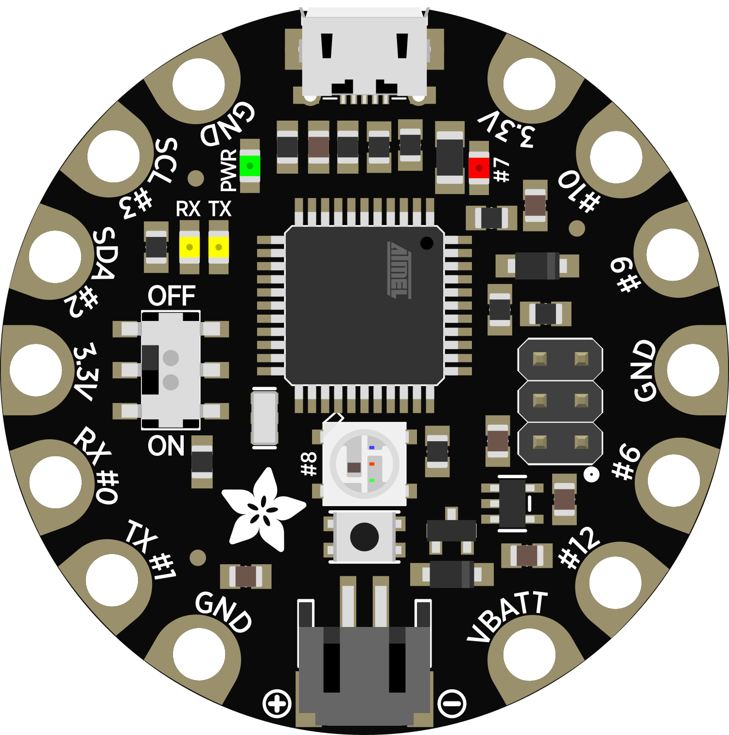
The Adafruit Flora v3 is a compact, user-friendly wearable electronic platform designed to enrich the world of e-textiles and wearable technology. It is built around the ATmega32u4 microcontroller, which is the same chip used in the popular Arduino Leonardo, making it fully compatible with Arduino software. The Flora is specifically engineered for sewing into clothing and fabric with conductive thread, and it can also be used with traditional electronic wires, sensors, and actuators for versatile project applications.

Explore Projects Built with Adafruit Flora v3

Use Cirkit Designer to design, explore, and prototype these projects online. Some projects support real-time simulation. Click "Open Project" to start designing instantly!
Battery-Powered Adafruit Flora RGB NeoPixel Light Show
Image of FloraTest: A project utilizing Adafruit Flora v3 in a practical application
This circuit consists of an Adafruit Flora v3 microcontroller connected to a Breadboard-friendly RGB Smart NeoPixel and powered by a 3xAAA battery pack. The microcontroller runs code to control the NeoPixel, displaying various colors and patterns.
Cirkit Designer LogoOpen Project in Cirkit Designer
Raspberry Pi 3B and Flora GPS-Based Real-Time Location Tracker
Image of prototype circuit: A project utilizing Adafruit Flora v3 in a practical application
This circuit connects a Flora GPS module to a Raspberry Pi 3B. The GPS module is powered by the Raspberry Pi's 3.3V and GND pins, and communicates with the Raspberry Pi via UART using the TX and RX pins.
Cirkit Designer LogoOpen Project in Cirkit Designer
Solar-Powered Environmental Data Logger with Adafruit Feather M0 Express
Image of Lake Thoreau Monitoring Station: A project utilizing Adafruit Flora v3 in a practical application
This circuit is designed for environmental data collection and logging, utilizing an Adafruit Feather M0 Express microcontroller as the central processing unit. It interfaces with a BME280 sensor for atmospheric temperature, humidity, and pressure measurements, an SGP30 sensor for monitoring air quality (eCO2 and TVOC), and a STEMMA soil sensor for detecting soil moisture and temperature. The system is powered by a solar panel and a 3.7v LiPo battery, managed by an Adafruit BQ24074 Solar-DC-USB Lipo Charger, and provides easy access to the microcontroller's connections through an Adafruit Terminal Breakout FeatherWing.
Cirkit Designer LogoOpen Project in Cirkit Designer
NodeMCU ESP8266 Water Flow Monitoring System with OLED Display and Alert Indicators
Image of IoT: A project utilizing Adafruit Flora v3 in a practical application
This circuit features a NodeMCU V3 ESP8266 microcontroller connected to a water flow sensor, an OLED display, a buzzer, and two LEDs (red and green). The water flow sensor's signal output is connected to a digital pin on the NodeMCU for flow measurement. The OLED display is interfaced via I2C with the NodeMCU, the buzzer is controlled by another digital pin for audio feedback, and the LEDs are used as status indicators, all powered by the NodeMCU's 3.3V supply.
Cirkit Designer LogoOpen Project in Cirkit Designer

Explore Projects Built with Adafruit Flora v3

Use Cirkit Designer to design, explore, and prototype these projects online. Some projects support real-time simulation. Click "Open Project" to start designing instantly!
Image of FloraTest: A project utilizing Adafruit Flora v3 in a practical application
Battery-Powered Adafruit Flora RGB NeoPixel Light Show
This circuit consists of an Adafruit Flora v3 microcontroller connected to a Breadboard-friendly RGB Smart NeoPixel and powered by a 3xAAA battery pack. The microcontroller runs code to control the NeoPixel, displaying various colors and patterns.
Cirkit Designer LogoOpen Project in Cirkit Designer
Image of prototype circuit: A project utilizing Adafruit Flora v3 in a practical application
Raspberry Pi 3B and Flora GPS-Based Real-Time Location Tracker
This circuit connects a Flora GPS module to a Raspberry Pi 3B. The GPS module is powered by the Raspberry Pi's 3.3V and GND pins, and communicates with the Raspberry Pi via UART using the TX and RX pins.
Cirkit Designer LogoOpen Project in Cirkit Designer
Image of Lake Thoreau Monitoring Station: A project utilizing Adafruit Flora v3 in a practical application
Solar-Powered Environmental Data Logger with Adafruit Feather M0 Express
This circuit is designed for environmental data collection and logging, utilizing an Adafruit Feather M0 Express microcontroller as the central processing unit. It interfaces with a BME280 sensor for atmospheric temperature, humidity, and pressure measurements, an SGP30 sensor for monitoring air quality (eCO2 and TVOC), and a STEMMA soil sensor for detecting soil moisture and temperature. The system is powered by a solar panel and a 3.7v LiPo battery, managed by an Adafruit BQ24074 Solar-DC-USB Lipo Charger, and provides easy access to the microcontroller's connections through an Adafruit Terminal Breakout FeatherWing.
Cirkit Designer LogoOpen Project in Cirkit Designer
Image of IoT: A project utilizing Adafruit Flora v3 in a practical application
NodeMCU ESP8266 Water Flow Monitoring System with OLED Display and Alert Indicators
This circuit features a NodeMCU V3 ESP8266 microcontroller connected to a water flow sensor, an OLED display, a buzzer, and two LEDs (red and green). The water flow sensor's signal output is connected to a digital pin on the NodeMCU for flow measurement. The OLED display is interfaced via I2C with the NodeMCU, the buzzer is controlled by another digital pin for audio feedback, and the LEDs are used as status indicators, all powered by the NodeMCU's 3.3V supply.
Cirkit Designer LogoOpen Project in Cirkit Designer

Common Applications and Use Cases

  • Wearable devices
  • Interactive fashion
  • Smart accessories
  • Educational projects
  • Prototyping e-textiles
  • DIY electronics

Technical Specifications

Key Technical Details

  • Microcontroller: ATmega32u4
  • Operating Voltage: 3.3V
  • Input Voltage (recommended): 3.5V to 16V (via JST battery connector)
  • Input Voltage (limits): 3.3V to 5V (via USB)
  • Digital I/O Pins: 9 (including 4 PWM channels)
  • Analog Input Pins: 4
  • DC Current per I/O Pin: 40 mA
  • Flash Memory: 32 KB (ATmega32u4) of which 4 KB used by bootloader
  • SRAM: 2.5 KB (ATmega32u4)
  • EEPROM: 1 KB (ATmega32u4)
  • Clock Speed: 8 MHz

Pin Configuration and Descriptions

Pin Number Name Description
1 GND Ground pin, used for circuit completion
2 VBATT Battery input for an external power source
3 D3 Digital I/O, PWM capable
4 D2 Digital I/O
5 D1/TX Digital I/O, UART transmit
6 D0/RX Digital I/O, UART receive
7 SDA I2C data line
8 SCL I2C clock line
9 D9 Digital I/O, PWM capable
10 D10 Digital I/O, PWM capable
11 D6 Digital I/O, PWM capable
12 D12 Digital I/O
13 # Not connected
14 A5 Analog input
15 A4 Analog input
16 A3 Analog input
17 A2 Analog input
18 3.3V 3.3V power output
19 RST Reset pin

Usage Instructions

How to Use the Component in a Circuit

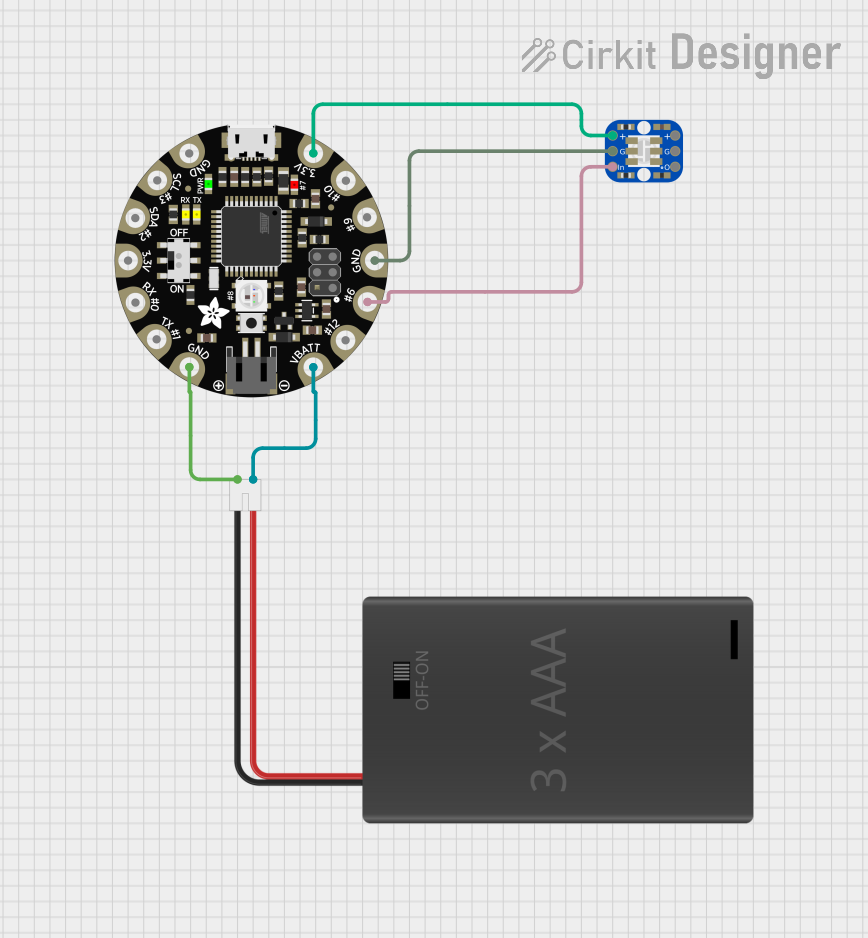
  1. Powering the Flora: Connect a 3.5V to 16V battery to the JST connector or power the Flora via the USB port.
  2. Programming: Use the Arduino IDE to write and upload sketches to the Flora. Select "Adafruit Flora" from the Tools > Board menu.
  3. Connecting Sensors/Actuators: Use conductive thread or solder to attach components to the Flora's sewable pads.
  4. Integration with Fabric: Sew the Flora onto your fabric using conductive thread, ensuring no short circuits between the pads.

Important Considerations and Best Practices

  • Always disconnect the battery before sewing or soldering to the Flora.
  • Avoid overlapping conductive threads to prevent short circuits.
  • Use a multimeter to check for shorts before powering your project.
  • Keep the Flora and connected components away from water and moisture.
  • When washing wearable projects, remove the battery and ensure the Flora is adequately protected.

Troubleshooting and FAQs

Common Issues

  • Flora not recognized by computer: Ensure the micro-USB cable is data-capable and the Flora is properly connected.
  • Short circuits or erratic behavior: Check for overlapping conductive threads or solder bridges between pads.
  • Inconsistent power: Verify the battery is charged and the JST connection is secure.

Solutions and Tips for Troubleshooting

  • Use a fresh, quality micro-USB cable for programming and ensure drivers are installed.
  • Conduct a visual inspection and use a multimeter to check for shorts.
  • If using conductive thread, ensure knots are secure and connections are not loose.

FAQs

Q: Can I power the Flora with a USB cable? A: Yes, the Flora can be powered via USB when connected to a computer or USB power source.

Q: Is the Flora washable? A: The Flora itself is not washable, but it can be made washable by using waterproof coatings and enclosures for the electronics.

Q: How do I connect the Flora to a computer? A: Connect the Flora to a computer using a micro-USB cable capable of data transfer.

Q: What programming language is used for the Flora? A: The Flora is programmed using Arduino C/C++, which is supported by the Arduino IDE.

Example Code for Arduino UNO

Here is a simple example of how to blink an LED connected to pin D9 on the Flora:

// Define the LED pin
const int ledPin = 9;

void setup() {
  // Set the LED pin as an output
  pinMode(ledPin, OUTPUT);
}

void loop() {
  // Turn the LED on
  digitalWrite(ledPin, HIGH);
  // Wait for one second
  delay(1000);
  // Turn the LED off
  digitalWrite(ledPin, LOW);
  // Wait for one second
  delay(1000);
}

Remember to select "Adafruit Flora" from the Tools > Board menu in the Arduino IDE before uploading this sketch.