Cirkit Designer Logo
Cirkit Designer
Your all-in-one circuit design IDE
Home / 
Component Documentation

How to Use Enecoder, 2/12 Series, CMOS, 2.4 V to 12 V, DIP-18: Examples, Pinouts, and Specs

Image of Enecoder, 2/12 Series, CMOS, 2.4 V to 12 V, DIP-18
Cirkit Designer LogoDesign with Enecoder, 2/12 Series, CMOS, 2.4 V to 12 V, DIP-18 in Cirkit Designer

Introduction

The HT12E is a CMOS LSI encoder IC designed by Holtek Semiconductor for use in remote control system applications. It is capable of converting 12 bits of parallel data inputs into a serial output. When combined with a wireless transmitter and a corresponding decoder (such as the HT12D), it can serve as the basis for a simple wireless data link.

Explore Projects Built with Enecoder, 2/12 Series, CMOS, 2.4 V to 12 V, DIP-18

Use Cirkit Designer to design, explore, and prototype these projects online. Some projects support real-time simulation. Click "Open Project" to start designing instantly!
Configurable Battery-Powered RF Signal Transmitter with DIP Switch Settings
Image of fyp transmitter: A project utilizing Enecoder, 2/12 Series, CMOS, 2.4 V to 12 V, DIP-18 in a practical application
This circuit appears to be a configurable encoder system with an RF transmission capability. The encoder's address pins (A0-A7) are connected to a DIP switch for setting the address, and its data output (DO) is connected to an RF transmitter, allowing the encoded signal to be wirelessly transmitted. The circuit is powered by a 9V battery, regulated to 5V by a 7805 voltage regulator, and includes a diode for polarity protection. Tactile switches are connected to the encoder's data inputs (D1-D3), and an LED with a current-limiting resistor indicates power or activity.
Cirkit Designer LogoOpen Project in Cirkit Designer
Arduino-Controlled 4-Channel RF Decoder Data Display with I2C LCD Interface
Image of FYP: A project utilizing Enecoder, 2/12 Series, CMOS, 2.4 V to 12 V, DIP-18 in a practical application
This circuit comprises an Arduino UNO microcontroller interfaced with four 2-to-12 series CMOS decoders, a 433 MHz RF receiver module, four 1MΩ resistors, four red LEDs, and a 20x4 I2C LCD display. The Arduino reads 3-bit data from each decoder, which are likely receiving signals from the RF receiver, and displays the binary data on the LCD. The LEDs are connected to the decoders' VT (valid transmission) pins, indicating successful data reception, and the entire circuit is powered by a 5V DC source.
Cirkit Designer LogoOpen Project in Cirkit Designer
Digital Logic State Indicator with Flip-Flops and Logic Gates
Image of 2-bit Gray Code Counter: A project utilizing Enecoder, 2/12 Series, CMOS, 2.4 V to 12 V, DIP-18 in a practical application
This circuit is a digital logic system that uses a DIP switch to provide input to a network of flip-flops and logic gates, which process the input signals. The output of this processing is likely indicated by LEDs, which are connected through resistors to limit current. The circuit functions autonomously without a microcontroller, relying on the inherent properties of the digital components to perform its logic operations.
Cirkit Designer LogoOpen Project in Cirkit Designer
Multi-Stage Voltage Regulation and Indicator LED Circuit
Image of Subramanyak_Power_Circuit: A project utilizing Enecoder, 2/12 Series, CMOS, 2.4 V to 12 V, DIP-18 in a practical application
This circuit is designed for power management, featuring buck and boost converters for voltage adjustment, and linear regulators for stable voltage output. It includes LEDs for status indication, and terminal blocks for external connections.
Cirkit Designer LogoOpen Project in Cirkit Designer

Explore Projects Built with Enecoder, 2/12 Series, CMOS, 2.4 V to 12 V, DIP-18

Use Cirkit Designer to design, explore, and prototype these projects online. Some projects support real-time simulation. Click "Open Project" to start designing instantly!
Image of fyp transmitter: A project utilizing Enecoder, 2/12 Series, CMOS, 2.4 V to 12 V, DIP-18 in a practical application
Configurable Battery-Powered RF Signal Transmitter with DIP Switch Settings
This circuit appears to be a configurable encoder system with an RF transmission capability. The encoder's address pins (A0-A7) are connected to a DIP switch for setting the address, and its data output (DO) is connected to an RF transmitter, allowing the encoded signal to be wirelessly transmitted. The circuit is powered by a 9V battery, regulated to 5V by a 7805 voltage regulator, and includes a diode for polarity protection. Tactile switches are connected to the encoder's data inputs (D1-D3), and an LED with a current-limiting resistor indicates power or activity.
Cirkit Designer LogoOpen Project in Cirkit Designer
Image of FYP: A project utilizing Enecoder, 2/12 Series, CMOS, 2.4 V to 12 V, DIP-18 in a practical application
Arduino-Controlled 4-Channel RF Decoder Data Display with I2C LCD Interface
This circuit comprises an Arduino UNO microcontroller interfaced with four 2-to-12 series CMOS decoders, a 433 MHz RF receiver module, four 1MΩ resistors, four red LEDs, and a 20x4 I2C LCD display. The Arduino reads 3-bit data from each decoder, which are likely receiving signals from the RF receiver, and displays the binary data on the LCD. The LEDs are connected to the decoders' VT (valid transmission) pins, indicating successful data reception, and the entire circuit is powered by a 5V DC source.
Cirkit Designer LogoOpen Project in Cirkit Designer
Image of 2-bit Gray Code Counter: A project utilizing Enecoder, 2/12 Series, CMOS, 2.4 V to 12 V, DIP-18 in a practical application
Digital Logic State Indicator with Flip-Flops and Logic Gates
This circuit is a digital logic system that uses a DIP switch to provide input to a network of flip-flops and logic gates, which process the input signals. The output of this processing is likely indicated by LEDs, which are connected through resistors to limit current. The circuit functions autonomously without a microcontroller, relying on the inherent properties of the digital components to perform its logic operations.
Cirkit Designer LogoOpen Project in Cirkit Designer
Image of Subramanyak_Power_Circuit: A project utilizing Enecoder, 2/12 Series, CMOS, 2.4 V to 12 V, DIP-18 in a practical application
Multi-Stage Voltage Regulation and Indicator LED Circuit
This circuit is designed for power management, featuring buck and boost converters for voltage adjustment, and linear regulators for stable voltage output. It includes LEDs for status indication, and terminal blocks for external connections.
Cirkit Designer LogoOpen Project in Cirkit Designer

Common Applications and Use Cases

  • Remote control systems for TVs, DVD players, and home automation
  • Wireless doorbells and security systems
  • Telemetry and remote sensing
  • Robotics communication interfaces

Technical Specifications

Key Technical Details

  • Operating Voltage: 2.4V to 12V
  • Low Power Consumption
  • Transmission Code: 12-bit
  • Oscillator Frequency: 1MHz (typical)
  • CMOS Technology for low power consumption

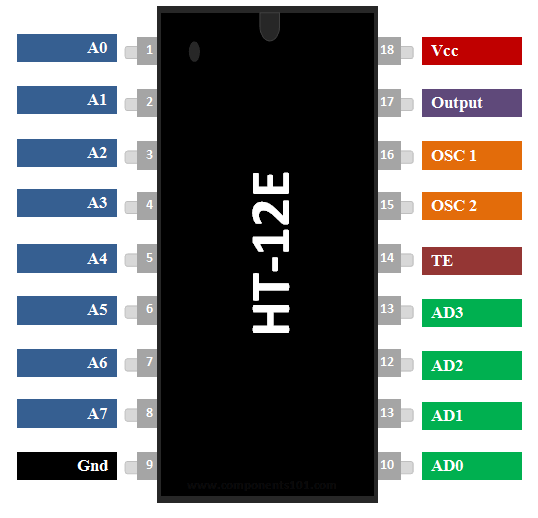
Pin Configuration and Descriptions

Pin Number Name Description
1-8 A0-A7 Address/Data pins. Set by external circuitry to define the transmitted address.
9 GND Ground reference voltage (0V).
10-13 AD8-AD11 Address/Data pins. Set by external circuitry to define the transmitted address.
14 OSC2 Oscillator input. Connected to a resistor for oscillator frequency setting.
15 OSC1 Oscillator output. Connected to a resistor for oscillator frequency setting.
16 TE Transmission Enable. Active low input used to enable or disable the transmission.
17 DOUT Serial Data Output. Transmits the encoded data when TE is low.
18 VDD Positive power supply voltage.

Usage Instructions

How to Use the Component in a Circuit

  1. Connect VDD (pin 18) to a 2.4V to 12V power supply.
  2. Connect GND (pin 9) to the ground of the power supply.
  3. Set the address/data pins (A0-A7 and AD8-AD11) to the desired binary high/low configuration using switches or jumpers.
  4. Connect an external resistor between OSC1 (pin 15) and OSC2 (pin 14) to set the oscillator frequency.
  5. Connect TE (pin 16) to a control switch or microcontroller output pin to enable/disable transmission.
  6. Connect DOUT (pin 17) to the data input of a wireless transmitter module.

Important Considerations and Best Practices

  • Ensure that the power supply voltage is within the specified range (2.4V to 12V).
  • The address pins must match the corresponding decoder (HT12D) for the system to function correctly.
  • Avoid long wires on the oscillator pins to prevent noise pickup.
  • Use a decoupling capacitor close to the VDD pin to filter out power supply noise.
  • The transmission enable (TE) pin should be kept high when not transmitting to reduce power consumption.

Troubleshooting and FAQs

Common Issues Users Might Face

  • No Output Signal: Ensure that the TE pin is pulled low to enable transmission. Check the power supply and oscillator frequency.
  • Intermittent Operation: Verify that all connections are secure and that there is no interference from nearby electronic devices.
  • Mismatched Address/Data: Confirm that the address/data settings on the encoder match those on the corresponding decoder.

Solutions and Tips for Troubleshooting

  • Double-check the power supply voltage and connections.
  • Ensure that the oscillator frequency is set correctly according to the datasheet.
  • Use a multimeter to verify the logic levels on the address/data pins.
  • If using a wireless transmitter, confirm that it is functioning properly and within range.

FAQs

Q: Can I use the HT12E without a microcontroller? A: Yes, the HT12E can be used with simple switches or buttons to set the address/data pins.

Q: What should I do if I experience interference in my wireless system? A: Try changing the address/data code to a different combination, and ensure that the antenna on the transmitter and receiver is optimized for the frequency of operation.

Q: How do I choose the resistor value for the oscillator? A: Refer to the HT12E datasheet for the formula to calculate the resistor value based on the desired oscillator frequency.

Example Code for Arduino UNO

// Example code for interfacing HT12E with Arduino UNO for data transmission

#define TE_PIN 2 // Transmission Enable pin connected to Arduino pin 2

void setup() {
  pinMode(TE_PIN, OUTPUT);
  // Set TE_PIN as output to control the Transmission Enable of HT12E
}

void loop() {
  // Begin transmission by pulling TE low
  digitalWrite(TE_PIN, LOW);
  
  // Insert code here to set the address/data pins as needed
  
  // End transmission by pulling TE high
  digitalWrite(TE_PIN, HIGH);
  
  // Wait for some time before the next transmission
  delay(1000);
}

Note: This example assumes that the address/data pins are directly controlled by the user. In a practical application, these pins would be connected to switches or connected to other digital pins on the Arduino for more dynamic control.