How to Use FS-R6B 6H RECEIVER: Examples, Pinouts, and Specs
Introduction
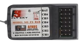
The FS-R6B 6H Receiver, manufactured by KEN, is a 6-channel receiver designed for use in radio-controlled models. It receives signals from a compatible transmitter and controls various functions such as throttle, steering, and other auxiliary controls. This receiver is commonly used in RC cars, boats, planes, and drones.
Explore Projects Built with FS-R6B 6H RECEIVER
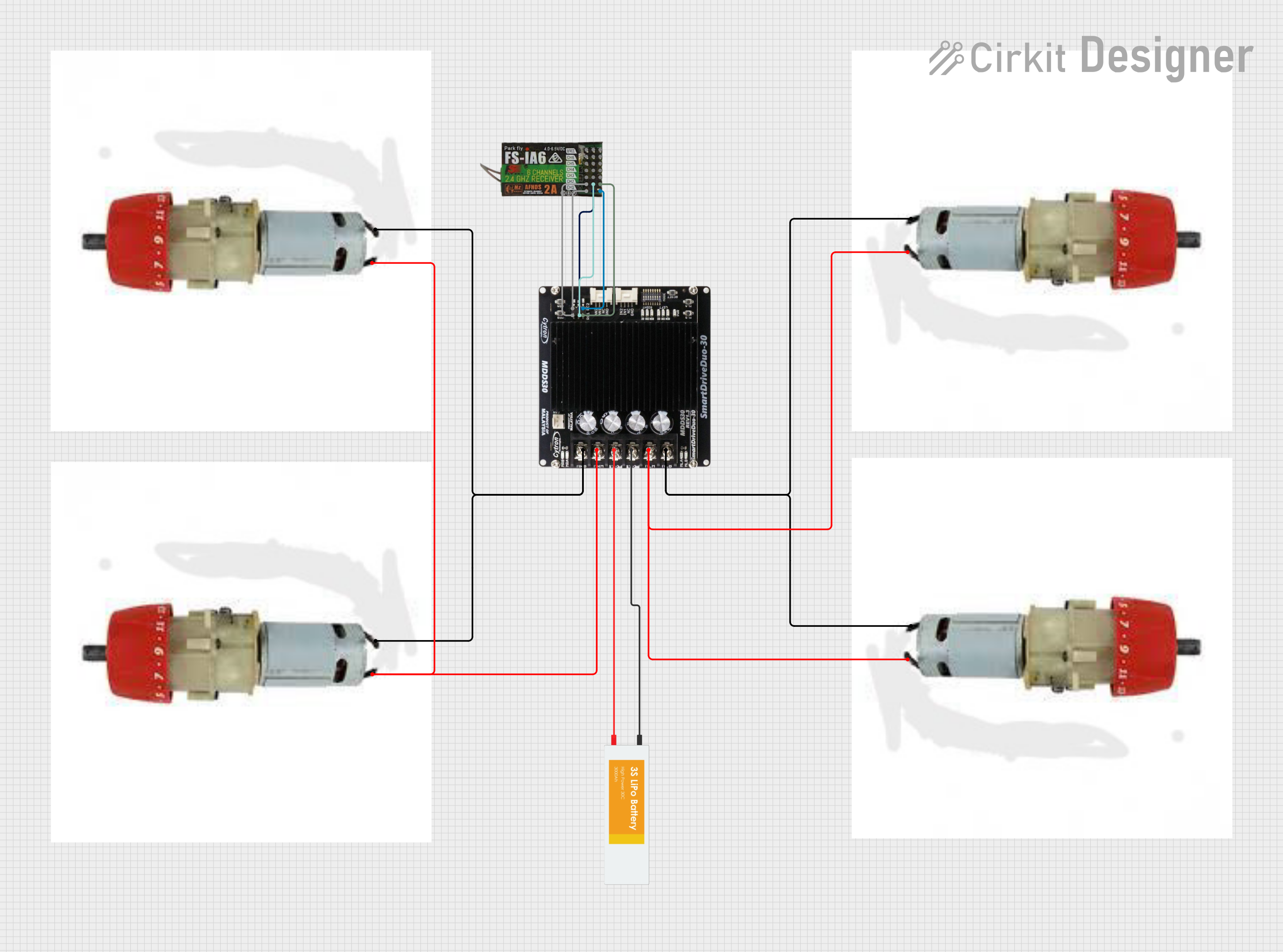
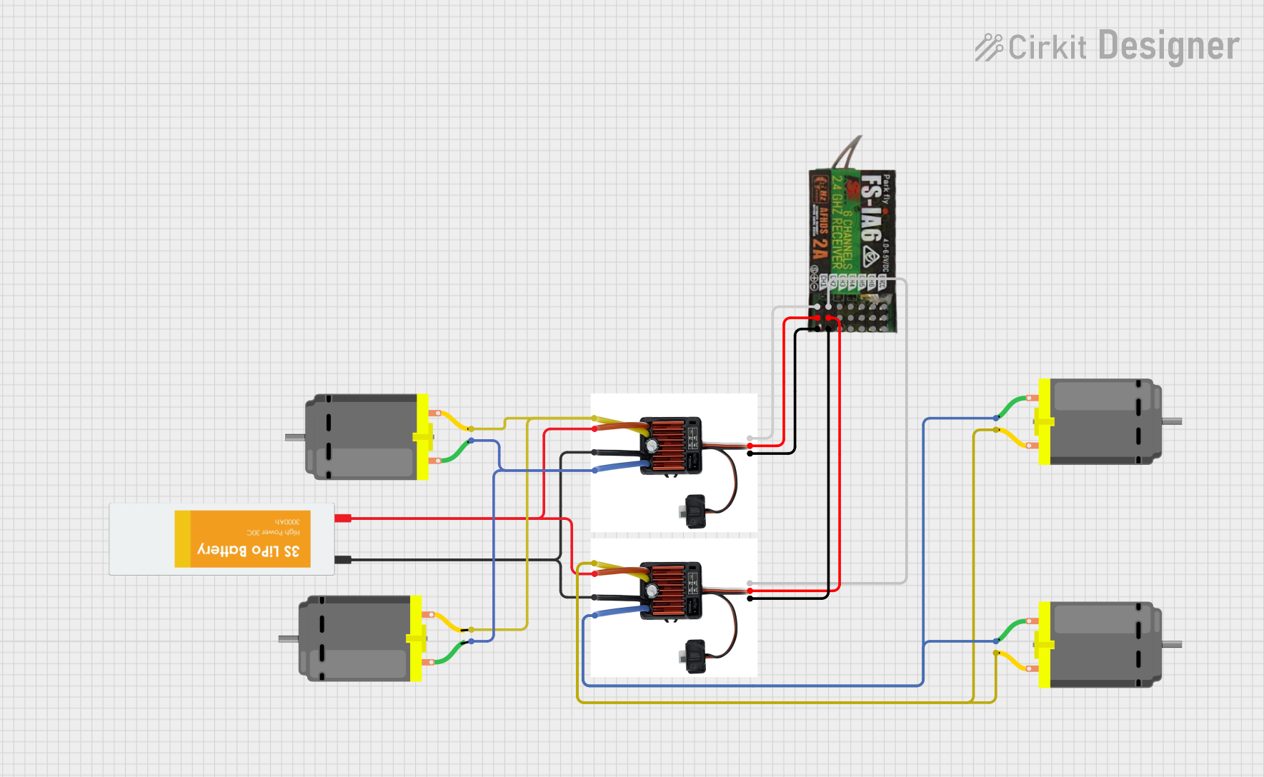


Explore Projects Built with FS-R6B 6H RECEIVER
Technical Specifications
Key Technical Details
| Specification | Value |
|---|---|
| Manufacturer | KEN |
| Part ID | 6 CHANNEL RECEIVER |
| Channels | 6 |
| Operating Voltage | 4.8V - 6.0V |
| Operating Current | ≤30mA |
| Frequency Range | 2.4GHz |
| Modulation Type | GFSK |
| Dimensions | 35mm x 22mm x 12mm |
| Weight | 10g |
| Antenna Length | 26mm |
Pin Configuration and Descriptions
| Pin Number | Pin Name | Description |
|---|---|---|
| 1 | CH1 | Channel 1 Signal Output |
| 2 | CH2 | Channel 2 Signal Output |
| 3 | CH3 | Channel 3 Signal Output |
| 4 | CH4 | Channel 4 Signal Output |
| 5 | CH5 | Channel 5 Signal Output |
| 6 | CH6 | Channel 6 Signal Output |
| 7 | VCC | Power Supply (4.8V - 6.0V) |
| 8 | GND | Ground |
Usage Instructions
How to Use the Component in a Circuit
- Power Supply: Connect the VCC pin to a power source within the range of 4.8V to 6.0V. Connect the GND pin to the ground of the power source.
- Signal Connections: Connect the signal pins (CH1 to CH6) to the corresponding control inputs of your RC model's servos, ESCs, or other control devices.
- Antenna: Ensure the antenna is properly positioned to receive signals from the transmitter without obstruction.
Important Considerations and Best Practices
- Power Supply: Ensure the power supply voltage is within the specified range to avoid damaging the receiver.
- Signal Interference: Keep the receiver away from high-power electronics to minimize signal interference.
- Antenna Positioning: Position the antenna in a way that maximizes signal reception and minimizes obstructions.
- Binding: Follow the binding procedure specific to your transmitter to ensure proper communication with the receiver.
Example: Connecting to an Arduino UNO
To use the FS-R6B 6H Receiver with an Arduino UNO, you can connect the signal pins to the digital input pins of the Arduino. Below is an example code to read the signal from Channel 1 and print the pulse width to the Serial Monitor.
// FS-R6B 6H Receiver - Arduino UNO Example
// Connect CH1 to Arduino pin 2

const int ch1Pin = 2; // Channel 1 signal pin
unsigned long pulseWidth;

void setup() {
  Serial.begin(9600); // Initialize serial communication
  pinMode(ch1Pin, INPUT); // Set CH1 pin as input
}

void loop() {
  pulseWidth = pulseIn(ch1Pin, HIGH); // Read pulse width from CH1
  Serial.print("CH1 Pulse Width: ");
  Serial.println(pulseWidth); // Print pulse width to Serial Monitor
  delay(100); // Delay for readability
}
Troubleshooting and FAQs
Common Issues Users Might Face
- No Signal Reception: The receiver is not receiving signals from the transmitter.
- Intermittent Signal: The signal is received intermittently, causing erratic control.
- Power Issues: The receiver does not power on or resets frequently.
Solutions and Tips for Troubleshooting
No Signal Reception:
- Ensure the transmitter and receiver are properly bound.
- Check the antenna positioning and ensure it is not obstructed.
- Verify the transmitter is powered on and within range.
Intermittent Signal:
- Check for sources of interference and move the receiver away from high-power electronics.
- Ensure the power supply is stable and within the specified voltage range.
Power Issues:
- Verify the power supply voltage is within the 4.8V to 6.0V range.
- Check the connections to the VCC and GND pins for any loose or faulty wiring.
FAQs
Q: Can I use the FS-R6B 6H Receiver with any 2.4GHz transmitter? A: The receiver is compatible with transmitters that use the same modulation type (GFSK) and frequency range (2.4GHz). Ensure your transmitter is compatible before use.
Q: How do I bind the receiver to my transmitter? A: Follow the binding procedure specific to your transmitter model. Typically, this involves powering on the receiver while holding a bind button or using a bind plug.
Q: What is the maximum range of the FS-R6B 6H Receiver? A: The maximum range depends on the transmitter and environmental conditions. Typically, it can range from 100 meters to several hundred meters in open areas.
Q: Can I use the receiver with a different power supply voltage? A: No, the receiver should only be used with a power supply voltage within the specified range of 4.8V to 6.0V to avoid damage.
This documentation provides a comprehensive guide to using the FS-R6B 6H Receiver. Whether you are a beginner or an experienced user, following these instructions and best practices will help you achieve optimal performance in your radio-controlled models.