
How to Use Breaker 4p: Examples, Pinouts, and Specs
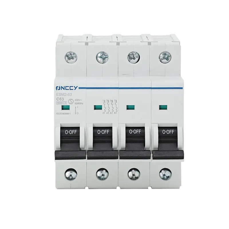
 Design with Breaker 4p in Cirkit Designer
Introduction
The Breaker 4P by Chint is a 4-pole circuit breaker designed to protect electrical circuits from overloads and short circuits. It ensures the safe disconnection of power in multi-phase systems, making it an essential component in industrial, commercial, and residential electrical installations. This breaker is particularly suited for applications requiring the management of three-phase systems with a neutral line.
Explore Projects Built with Breaker 4p
 Open Project in Cirkit Designer
 Open Project in Cirkit Designer
 Open Project in Cirkit Designer
 Open Project in Cirkit Designer
Explore Projects Built with Breaker 4p
Open Project in Cirkit DesignerOpen Project in Cirkit DesignerOpen Project in Cirkit DesignerOpen Project in Cirkit DesignerCommon Applications and Use Cases
- Protection of three-phase electrical systems in industrial environments
- Overload and short circuit protection in commercial buildings
- Residential use for managing multi-phase power distribution
- Integration into control panels and distribution boards
- Ensuring safe disconnection during maintenance or emergencies
Technical Specifications
The following table outlines the key technical details of the Breaker 4P:
| Parameter | Specification |
|---|---|
| Manufacturer | Chint |
| Number of Poles | 4 |
| Rated Voltage (Ue) | 400V AC |
| Rated Current (In) | 10A, 16A, 25A, 32A, 40A, 63A (varies by model) |
| Breaking Capacity (Icu) | 10kA |
| Frequency | 50/60 Hz |
| Operating Temperature | -5°C to +40°C |
| Mounting Type | DIN Rail |
| Standards Compliance | IEC 60898-1, IEC 60947-2 |
Pin Configuration and Descriptions
The Breaker 4P has four terminals, each corresponding to a specific phase or neutral connection. The table below describes the pin configuration:
| Terminal | Description |
|---|---|
| L1 | Phase 1 input/output |
| L2 | Phase 2 input/output |
| L3 | Phase 3 input/output |
| N | Neutral input/output |
Usage Instructions
How to Use the Breaker 4P in a Circuit
- Mounting: Securely install the breaker onto a DIN rail in the distribution board or control panel.
- Wiring:
- Connect the incoming power supply lines (L1, L2, L3, and N) to the corresponding input terminals of the breaker.
- Connect the outgoing load lines to the corresponding output terminals.
- Ensure all connections are tight and secure to prevent arcing or overheating.
- Operation:
- Switch the breaker to the "ON" position to allow current flow.
- In case of an overload or short circuit, the breaker will automatically trip to the "OFF" position, disconnecting the circuit.
- Resetting:
- After addressing the fault, manually reset the breaker by switching it back to the "ON" position.
Important Considerations and Best Practices
- Current Rating: Ensure the breaker’s rated current matches the load requirements to avoid nuisance tripping or insufficient protection.
- Breaking Capacity: Verify that the breaking capacity (Icu) is sufficient for the maximum fault current in the system.
- Neutral Connection: Always connect the neutral line to the designated terminal (N) to ensure proper operation.
- Periodic Inspection: Regularly inspect the breaker for signs of wear, overheating, or loose connections.
- Safety: Always disconnect power before performing any wiring or maintenance tasks.
Example: Connecting the Breaker 4P to an Arduino UNO
While the Breaker 4P is not directly interfaced with microcontrollers like the Arduino UNO, it can be used in conjunction with relays or contactors to control high-power loads. Below is an example of how to use an Arduino UNO to control a relay that operates the breaker:
// Example code to control a relay using Arduino UNO
// This relay can be used to control the Breaker 4P indirectly

const int relayPin = 7; // Pin connected to the relay module

void setup() {
  pinMode(relayPin, OUTPUT); // Set relay pin as output
  digitalWrite(relayPin, LOW); // Ensure relay is off at startup
}

void loop() {
  // Turn on the relay (simulate closing the breaker)
  digitalWrite(relayPin, HIGH);
  delay(5000); // Keep the relay on for 5 seconds

  // Turn off the relay (simulate opening the breaker)
  digitalWrite(relayPin, LOW);
  delay(5000); // Keep the relay off for 5 seconds
}
Note: Ensure the relay module is rated for the voltage and current of the Breaker 4P's control circuit.
Troubleshooting and FAQs
Common Issues and Solutions
| Issue | Possible Cause | Solution |
|---|---|---|
| Breaker trips frequently | Overload or short circuit in the circuit | Check the load and wiring for faults. |
| Breaker does not trip during a fault | Incorrect current rating or faulty breaker | Verify the breaker rating and replace if necessary. |
| Overheating of terminals | Loose connections | Tighten all terminal screws securely. |
| Difficulty resetting the breaker | Persistent fault in the circuit | Inspect and resolve the fault before resetting. |
FAQs
Can the Breaker 4P be used for single-phase systems?
- Yes, but it is primarily designed for three-phase systems. For single-phase use, connect only one phase and the neutral.
What is the difference between a 3-pole and a 4-pole breaker?
- A 3-pole breaker protects three phases (L1, L2, L3), while a 4-pole breaker also includes protection for the neutral line (N).
How do I determine the correct breaker rating for my application?
- Calculate the total load current and select a breaker with a rated current slightly higher than the load but within safe limits.
Can the breaker be used outdoors?
- The breaker itself is not weatherproof. Use it in an enclosure rated for outdoor use if required.
By following this documentation, users can effectively integrate and maintain the Breaker 4P in their electrical systems.